Vehicle-mounted loop antenna apparatus and manufacturing method thereof

A loop antenna and antenna seat technology, applied in the direction of antenna support/mounting device, antenna grounding switch structure connection, welding/welding connection, etc., can solve the problems of antenna swing, easy to desoldering, etc. Soldering and desoldering, the effect of large contact area

Active Publication Date: 2014-02-26
NANJING UNIV OF AERONAUTICS & ASTRONAUTICS
View PDF3 Cites 1 Cited by
  • Summary
  • Abstract
  • Description
  • Claims
  • Application Information

AI Technical Summary

Problems solved by technology

[0005] In order to solve the problem that the vehicle-mounted antenna is prone to desoldering and antenna swing due to the unfavorable environment such as vibration and impact of the external environment during use, the present invention proposes a vehicle-mounted annular antenna suitable for vibration and impact. Antenna device and manufacturing method thereof

Method used


Image

  • Vehicle-mounted loop antenna apparatus and manufacturing method thereof
  • Vehicle-mounted loop antenna apparatus and manufacturing method thereof
  • Vehicle-mounted loop antenna apparatus and manufacturing method thereof

Examples


Embodiment Construction

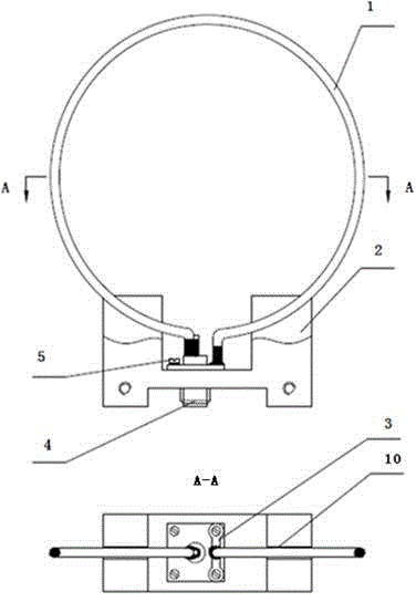
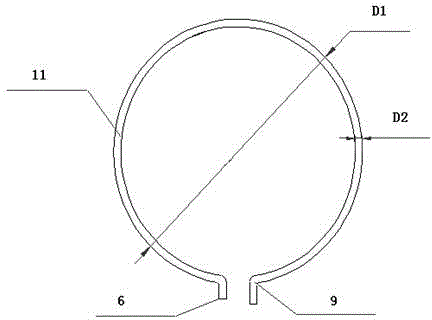
[0024] Please refer to Figure 1 to Figure 4 As shown, the vehicle-mounted loop antenna device of the present invention includes: an antenna vibrator 1 , an antenna base 2 and a high-frequency connector 4 . The antenna vibrator 1 includes an antenna vibrator metal ring 11, an antenna vibrator short solder leg 6 and an antenna vibrator long solder leg 9, wherein the antenna vibrator short solder leg 6 is welded to the high frequency connector socket solder pin 7, and the antenna vibrator long solder leg 9 Welded with the high-frequency connector flange plate, it adopts unique structural design and process to ensure the welding effect.

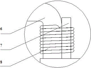
[0025] In the vehicle-mounted loop antenna device of the present invention, the short welding leg 6 of the antenna vibrator and the welding pin 7 of the high-frequency connector socket are overlapped, and then the bare copper wire 8 is wound firmly and then welded, which effectively increases the short welding leg 6 of the antenna vibrator and t...


PUM


Abstract

The invention provides a vehicle-mounted loop antenna apparatus and a manufacturing method thereof. The apparatus comprises an antenna oscillator, an antenna base and a high frequency connector, wherein the antenna oscillator and the high frequency connector are installed on the antenna base; the antenna oscillator comprises a metal ring, a short welding foot and a long welding foot; the high frequency connector comprises a high frequency connector socket welding needle, a high frequency connector flange plate and the like; and the short welding foot of the antenna oscillator and the high frequency connector socket welding needle are overlapped, are wound firmly through a bare copper wire and then are welded. The vehicle-mounted loop antenna apparatus is characterized by further comprising a plurality of welding sheets. One end of each welding sheet is fixed to the high frequency connector flange plate; the non-fixed end of each welding sheet is bent by an angle of 90 degrees towards the direction of the antenna oscillator; the distances between the bending parts of the welding sheets are the diameter of a antenna oscillator material; and the long welding foot of the antenna oscillator is inserted to the vertically bent butt joint position of the rail ends of the welding sheets and is firmly connected with the high frequency connector flange plate in a welding mode. The apparatus and the method provided by the invention solve the problems of easy unsoldering, antenna swinging and the like caused by unfavorable environments of vibration and impact of an external environment and the like during a use process of a conventional vehicle-mounted antenna.

Description

technical field [0001] The invention relates to a vehicle-mounted loop antenna device and a manufacturing method thereof, belonging to the field of mechanical design. Background technique [0002] Chinese patent application CN200710027300.9 discloses a welding connection method for a line connector with double rows of connecting pins, which is completed by precise alignment lapping, welding and trimming between the soldering ends of the two rows of core wires and the corresponding soldering pins of the plug Accurate alignment and overlap of the solder pins realizes the welding connection between the solder pins of the plug and the solder ends of the core wires. However, in this welding connection method, the soldering pins of the antenna and the socket soldering pins of the high-frequency connector are overlapped and then soldered directly, and false soldering and desoldering are prone to occur in unfavorable environments such as vibration and impact. [0003] Most of the e...

Claims


Application Information

Patent Timeline
Patent Type & Authority Applications(China)
IPC IPC(8): H01Q1/12H01Q1/50H01R4/02
Inventor 王洪宪王少云王阳
Owner NANJING UNIV OF AERONAUTICS & ASTRONAUTICS
Why Eureka
Try Eureka