An automatic switch on a power distribution pole and its installation method

A technology for distribution poles and automation terminals, applied in the spatial arrangement/configuration of cables, fiber mechanical structure, etc., can solve problems affecting the use of automatic switches, signal interference, etc., and achieve beautiful construction, maintenance, installation specifications, and stress reduction. The effect of loss

Active Publication Date: 2016-03-09
STATE GRID CORP OF CHINA +3
View PDF10 Cites 0 Cited by
  • Summary
  • Abstract
  • Description
  • Claims
  • Application Information

AI Technical Summary

Problems solved by technology

[0004] However, after actual use, it is found that if the remaining cables are allowed to be freely wound on the "cable ferrule", it is very easy to cause signal interference due to the repeated superposition of the magnetic field generated when transmitting communication signals, which greatly affects the use of automated switches

Method used


Image

  • An automatic switch on a power distribution pole and its installation method
  • An automatic switch on a power distribution pole and its installation method
  • An automatic switch on a power distribution pole and its installation method

Examples


Embodiment Construction

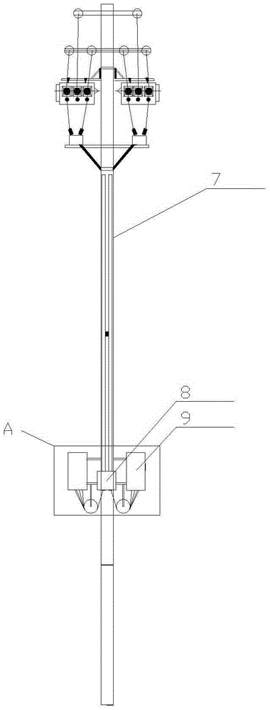
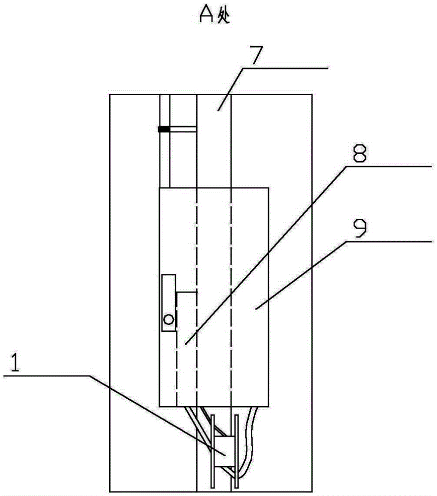
[0053] The present invention as Figure 1-12 As shown, it is connected to the middle part of the power distribution pole 7, and the top of the power distribution pole 7 is provided with high-voltage equipment; the switch includes an optical cable distribution box 8, a number of remaining cable racks and an intelligent power distribution automation terminal 9; The box 8 is connected to the high-voltage equipment through a secondary line, and connected to a pair of intelligent power distribution automation terminals 9 through the remaining cables of the secondary line;

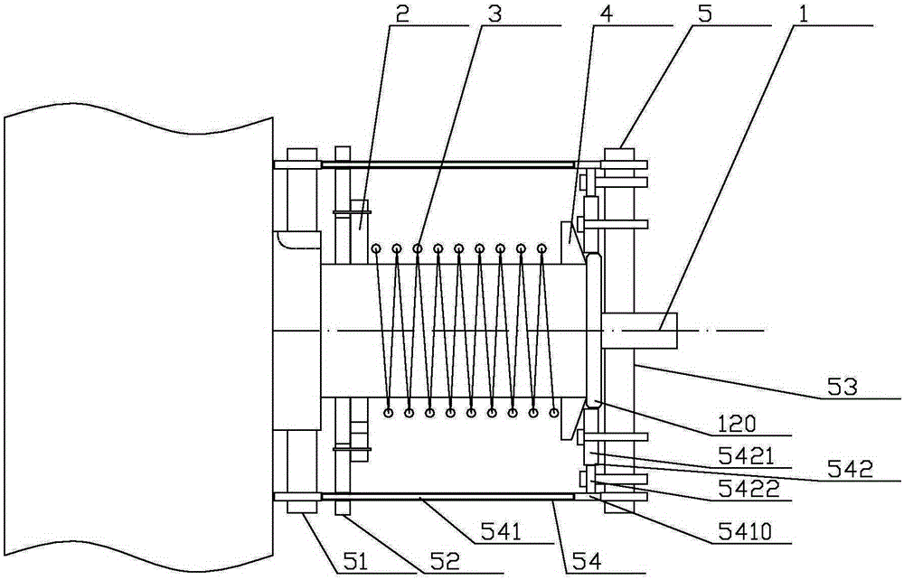
[0054] The remaining cable rack includes a ladder central axis 1, a pressing plate 2, a compression spring 3, a base plate 4 and a uniform wiring device 5 detachably connected to the ladder central axis; in this way, after the winding is completed, the uniform wiring can be removed The device makes the uniform wiring device reusable, thereby reducing the use cost and expanding the use range.

[0055] The steppe...


PUM


Abstract

The invention discloses an automatic switch on a power distribution rod and an installation method of the automatic switch, relating to the field of support equipment of a high-voltage line. The automatic switch is connected to the middle of the power distribution rod, high-voltage equipment is arranged at the top of the power distribution rod, the automatic switch comprises a cable branch box, a plurality of redundant cable frames and an intelligent power distribution automatic terminal, wherein each redundant cable frame comprises a step center shaft, a pressure plate, a pressure spring, a base plate and a uniform wiring device; the uniform wiring device comprises a movable internal board sleeved outside a center shaft I, a linkage board hollowly sleeved outside a center shaft II, and a movable board sleeved outside a center shaft III; at least one linkage device is arranged between the movable internal board and the movable external board. As a whole, the automatic switch has the characteristics of low manual strength when being used, and convenient and simple use method; after being wound, redundant cables can be neatly and uniformly wound on the center shaft II side by side; after being dismantled, the uniform wiring device is stably accommodated between the end face of the center shaft III and the pressure plate under the action of the pressure spring, and thus the problem that the redundant cables are influenced by magnetic fields generated by the redundant cables is effectively avoided.

Description

technical field [0001] The invention relates to the field of supporting equipment for high-voltage lines, in particular to the improvement of the remaining cable rack used to communicate with the secondary line of the automatic switch on the distribution pole. Background technique [0002] With the maturity of distribution automation technology, the automatic switch on the distribution pole has been widely used; however, the secondary line used to connect the automatic switch on the distribution pole has defects such as irregular installation process and unattractive appearance. . Specifically: after the installation, the secondary line is usually laid along the distribution pole and exposed to the outside, and the redundant secondary line (because the secondary line is a vulnerable part, it is usually reserved for 5-15 meters during installation) Quantities) hang haphazardly below automation switches. In this way, the secondary line seriously affects the daily pole mainte...

Claims


Application Information

Patent Timeline
Patent Type & Authority Patents(China)
IPC IPC(8): H02G7/20G02B6/44
Inventor 徐勇高晓宁汪鸿庭屈文扬胡俊邹婷婷孙叶旭童兆晖李文萍张蕾
Owner STATE GRID CORP OF CHINA
Why Eureka
Try Eureka