Thyristor dimming circuit and dimming control method

A silicon dimming and circuit technology, applied in electroluminescent light sources, lamp circuit layout, energy-saving control technology, etc., can solve problems such as LED light flickering, achieve linear dimming curves, and avoid LED light flickering effects

Active Publication Date: 2014-02-26
SILERGY SEMICON TECH (HANGZHOU) CO LTD
View PDF6 Cites 20 Cited by
  • Summary
  • Abstract
  • Description
  • Claims
  • Application Information

AI Technical Summary

Problems solved by technology

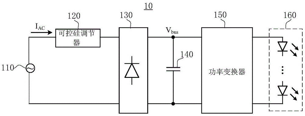
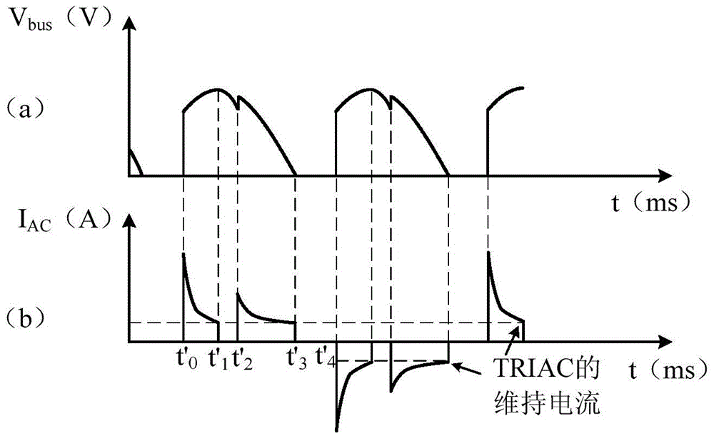
[0007] However, in the prior art, at t' 2 time, the restart of the TRIAC will affect the input power of the AC input power source 110, so that the bus voltage V of the power converter 150 bus Beating, causing the LED lights of the load 160 to flicker

Method used


Image

  • Thyristor dimming circuit and dimming control method
  • Thyristor dimming circuit and dimming control method
  • Thyristor dimming circuit and dimming control method

Examples


Embodiment Construction

[0057] In the interest of clarity, not all features of an actual implementation are described. In the following description, well-known functions and constructions are not described in detail since they would obscure the invention with unnecessary detail. It should be appreciated that in the development of any actual embodiment, numerous implementation details must be worked out to achieve the developer's specific goals, such as changing from one embodiment to another in accordance with system-related or business-related constraints. Additionally, it should be recognized that such a development effort might be complex and time consuming, but would nevertheless be merely a routine undertaking for those skilled in the art.

[0058] In the following paragraphs the invention is described more specifically by way of example with reference to the accompanying drawings. Advantages and features of the present invention will be apparent from the following description and claims. It s...


PUM


Abstract

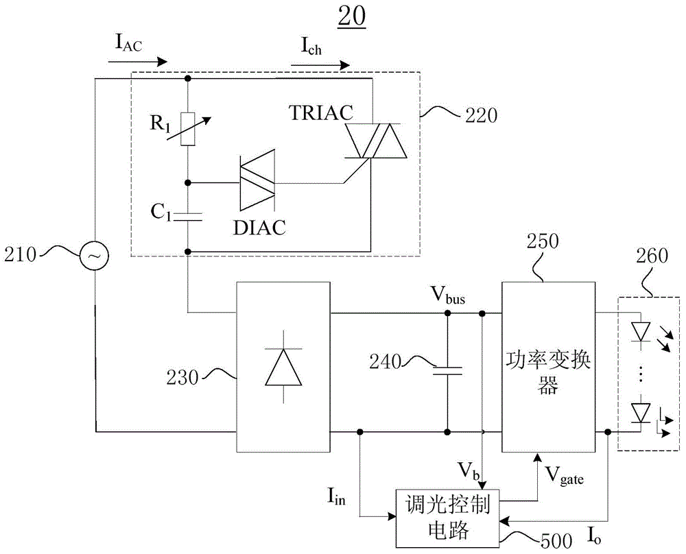
The invention discloses a thyristor dimming circuit. The thyristor dimming circuit comprises a thyristor adjuster, a rectifying circuit, a filter circuit, a power converter and a dimming control circuit. The dimming control circuit comprises a conduction angle detection circuit, an output current feedback control circuit, an input current control circuit, a maximum working time detection circuit and a logical operation circuit. The invention further discloses a dimming control method. The power converter is controlled to be turned on or turned off, so that after the thyristor adjuster is turned off, input current sampling signals always fluctuate around a preset value, and alternating current input currents are made to be smaller than the holding current of the thyristor adjuster. By the adoption of the thyristor dimming circuit and the dimming control method, the thyristor adjuster can be prevented from being repeatedly turned on within a work frequency period, a dimming curve is more linear, and an LED lamp is prevented from flickering.

Description

technical field [0001] The invention relates to the technical field of power regulation of electric equipment, in particular to a thyristor dimming circuit and a dimming control method. Background technique [0002] In the existing light control, silicon controlled rectifier regulators are generally used to control the on, off and brightness of the light. In the prior art, the thyristor dimming circuit 10 such as figure 1 As shown, the AC input power source 110 supplies energy to the load 160 after being processed by the thyristor regulator 120 , the rectifier circuit 130 , the filter capacitor 140 and the power converter 150 . [0003] exist figure 2 Among them, (a) represents the waveform schematic diagram of the bus voltage after the rectification circuit 130, wherein, the ordinate represents the voltage (V), and the abscissa represents the time t (ms); (b) represents the AC input current I AC The schematic diagram of the waveform, where the ordinate represents the cu...

Claims


Application Information

Patent Timeline
Patent Type & Authority Applications(China)
IPC IPC(8): H05B37/02H02M1/00H05B44/00
CPCY02B20/42H02M3/156H02M7/1557Y02B20/30H05B45/3725H02M1/007Y02B20/40
Inventor 邓建韩云龙黄晓东
Owner SILERGY SEMICON TECH (HANGZHOU) CO LTD
Why Eureka
Try Eureka