
Blade, particularly variable-pitch blade, propellor comprising such blades and corresponding turbomachine

A propeller and variable pitch technology, which is applied in the direction of propellers, mechanical equipment, aircraft parts, etc., can solve the problems of unstable propeller speed, damage to the aerodynamic performance of downstream propellers, and aggravate turbulent flow activities at the base of propeller blades, so as to reduce the intensity of noise, The effect of promoting performance improvement

Active Publication Date: 2014-02-26
SN DETUDE & DE CONSTR DE MOTEURS DAVIATION S N E C M A
View PDF5 Cites 9 Cited by
  • Summary
  • Abstract
  • Description
  • Claims
  • Application Information

AI Technical Summary

Problems solved by technology

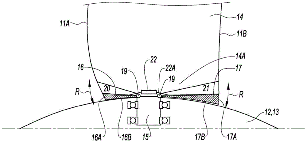
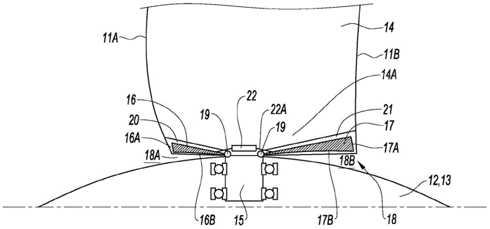
[0011] This space—determined by the upstream and downstream voids, the two regions being separated from each other by the root of each blade—exacerbates turbulent flow activity at the base of the propeller blades, especially when said propeller is tightly fastened (e.g., in during takeoff and approach), which further impairs the aerodynamic performance of the downstream propeller and increases said propeller speed instabilities, which are the cause of unwanted noise emissions

Method used


Image

  • Blade, particularly variable-pitch blade, propellor comprising such blades and corresponding turbomachine
  • Blade, particularly variable-pitch blade, propellor comprising such blades and corresponding turbomachine
  • Blade, particularly variable-pitch blade, propellor comprising such blades and corresponding turbomachine

Examples


Embodiment Construction

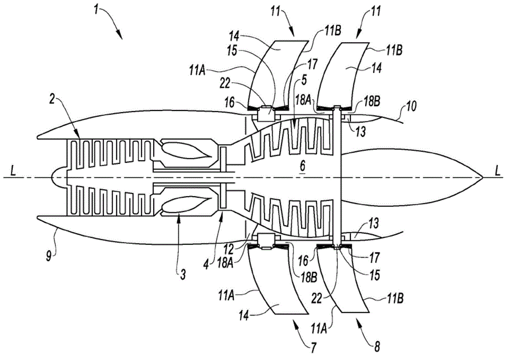
[0036] figure 1 Shown is an unducted fan turbine engine 1 according to the invention comprising a compressor 2, an annular combustion chamber 3, a high pressure turbine 4 and The two counter-rotating low-pressure turbines 5 and 6 , that is to say the low-pressure turbines 5 and 6 rotate about the longitudinal axis L-L in two opposite directions.

[0037] Each low-pressure turbine 5 and 6 is connected in a rotationally fixed manner to external propellers 7, 8 which extend radially to the outside of the nacelle 9 of the turbine engine 1, the nacelle 9 having a generally cylindrical shape surrounding the compressor 2, the combustion chamber 3 and turbines 4, 5 and 6 extend along the axis L-L. Combustion gases leaving the turbine are expelled via nozzle 10 to increase thrust.

[0038] The propellers 7 and 8 are coaxially arranged one behind the other and comprise a plurality of blades 11 equiangularly distributed around the longitudinal axis L-L. The blades 11 extend generally ...


PUM


Abstract

According to the invention, the blade (11), intended to be mounted on the hub (12, 13) of a turbomachine propeller so that an empty space (18, 18A, 18B) is defined between the base (14A) of the blade (14) and the face of the hub (12, 13) facing said base (14A), comprises retractable blanking means (16, 17) able reversibly to occupy at least one of the following two positions: - a deployed position in which the retractable blanking means at least partially blank off said empty space (18, 18A, 18B); and - an extreme retracted position in which said retractable means are kept out of said empty space.

Description

technical field [0001] The present invention relates to a blade, in particular to a variable-pitch blade, a propeller comprising the blade, and a corresponding turbine engine, especially a turbine engine without a ducted fan. Background technique [0002] While the invention is particularly suited to unducted fan turbine engines (also known as "open rotor" turbine engines), practice of the invention is by no means limited to application to such engines. [0003] In a known manner, the unducted fan turbine engine comprises, upstream (front) and downstream (rear) respectively, two coaxially counter-rotating external propellers, each rotated by the turbine and extending substantially radially to the turbine engine outside of the nacelle. Each propeller traditionally comprises a hub concentric with the longitudinal axis of the turbine engine, to which the blades are fixed. [0004] However, despite low fuel consumption, the aerodynamic interaction between upstream and downstre...

Claims


Application Information

Patent Timeline
Patent Type & Authority Applications(China)
IPC IPC(8): B64C11/18B64C11/30B64C11/48B64C11/20F02K3/02
CPCF01D7/00F05D2220/325B64C11/06B64C11/306Y02T50/66B64D2027/005Y02T50/673F05D2220/324Y02T50/60B64C11/20
Inventor 塞巴斯蒂安·帕斯卡尔
Owner SN DETUDE & DE CONSTR DE MOTEURS DAVIATION S N E C M A
Learn More