Hydrodynamic cavitation generating device

A generation device and hydraulic cavitation technology, applied in chemical instruments and methods, chemical/physical processes, chemical/physical/physical chemical processes, etc., can solve the problem of real-time observation of cavitation areas that are difficult to cavitate, and limit hydraulic cavitation technology Popularization and application, problems such as buffering and rectification of the incoming liquid, to achieve the effects of easy control and observation, wide practicability, and simple structure

Active Publication Date: 2014-03-05
CHINA UNIV OF MINING & TECH
View PDF14 Cites 10 Cited by
  • Summary
  • Abstract
  • Description
  • Claims
  • Application Information

AI Technical Summary

Problems solved by technology

[0004] At present, water conservancy cavitation devices mostly use Venturi tubes or porous plates with constricted throats as cavitation reactors. There are few reports that cavitation is generated by spoilers of different shapes, and it is difficult to achieve real-time observation of cavitation cavitation areas. The incoming liquid cannot be buffered and rectified, and it is even more difficult to ensure the strength and stability of the cavitation. Therefore, it affects the performance of the cavitation reaction device and limits the further promotion and application of the hydraulic cavitation technology.

Method used


Image

  • Hydrodynamic cavitation generating device
  • Hydrodynamic cavitation generating device
  • Hydrodynamic cavitation generating device

Examples


Embodiment Construction

[0020] An embodiment of the present invention will be described in further detail below in conjunction with accompanying drawing:

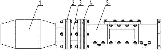
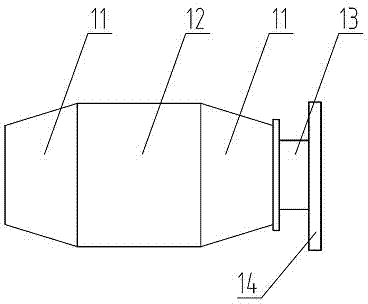
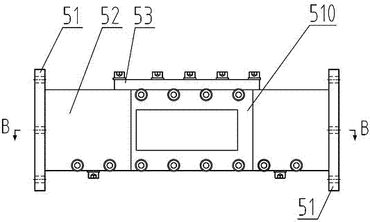
[0021] Such as figure 1 As shown, the hydraulic cavitation generating device of the present invention is mainly composed of a buffer body 1, a rectifier body 3 and a test body 5, and a rectification orifice plate 2 is arranged between the buffer body 1 and the rectifier body 3, and the rectifier body 3 and the test body A rectifying grid plate 4 is arranged between the body 5; the buffer body includes a buffer body circular tube 12, and both ends of the buffer body circular tube 12 are welded with a circular platform shell 11, and the circular platform shell 11 at one end passes through the buffer body square tube 3 is connected with buffer body flange 14, such as Figure 10 Shown; Described rectification orifice 2 is the square thin plate that is provided with a plurality of circular holes in the middle, and the circular hole of rectification or...


PUM


Abstract

The invention provides a hydrodynamic cavitation generating device. The hydrodynamic cavitation generating device comprises a buffering body, a rectifying pore plate, a rectifying body, a rectifying grid plate and a testing body which are connected by flanges in sequence, wherein the testing body is a fluid channel which is composed of a shell and a ladder-shaped bottom plate and has a square cross section; three observation windows which are as wide as the fluid channel are opened on front, back and upper sides of the testing body; a bottom plate is split and is provided with a turbulent flow platform. A coming liquid sequentially passes through the buffering body, the rectifying pore plate, the rectifying body and the rectifying grid plate, the turbulence intensity can be reduced and the stability of water flow is enhanced effectively, so that the coming liquid can stably enter the testing body. The hydrodynamic cavitation generating device is simple in structure, convenient to detach, high in structural strength and good in impermeability; a test piece and the turbulent flow platform are convenient to replace; the distance between the test piece and the turbulent flow platform is convenient to adjust; the turbulence intensity is small and the cavitation strength can be adjusted continuously; the cavitation property can be observed directly and easily.

Description

technical field [0001] The invention relates to a cavitation generating device, in particular to a hydraulic cavitation generating device suitable for use in hydraulic structures and ships. Background technique [0002] Cavitation refers to the process of the formation, development and collapse of vapor or gas cavities (cavitations) inside the liquid or on the liquid-solid interface when the local pressure in the fluid (liquid) drops. Since the discovery of cavitation on propeller blades in the second half of the 19th century, people have continued to study cavitation and cavitation erosion, and gradually realized that it is a multiphase, transient, and microscopic complex process, which has a great impact on hydraulic engineering. Buildings, ships, aerospace, aviation, etc. are very harmful, but so far the mechanism of cavitation cavitation has not been clearly studied, so scientific and technological workers from various countries are eager to conduct in-depth research on ...

Claims


Application Information

Patent Timeline
Patent Type & Authority Applications(China)
IPC IPC(8): B01J19/00
Inventor 刘秀梅贺杰石高亮李文华龙正李龙张婷婷
Owner CHINA UNIV OF MINING & TECH
Why Eureka
Try Eureka