
Linear guide rail sliding block

A linear guide rail slider and sliding seat technology, applied in the field of linear guide rails, can solve the problems of increased manufacturing costs, too many assembly steps, and low assembly efficiency

Active Publication Date: 2014-03-05
青岛祥银传动设备有限公司
View PDF6 Cites 2 Cited by
  • Summary
  • Abstract
  • Description
  • Claims
  • Application Information

AI Technical Summary

Problems solved by technology

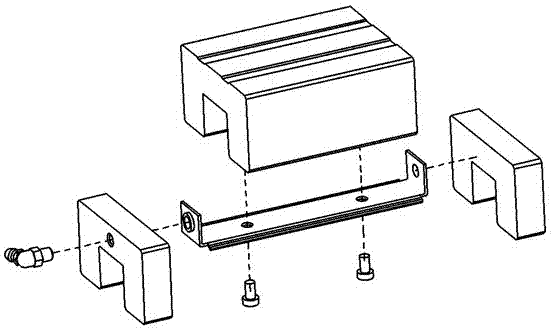
[0007] The second prior art omits the fixing part of the grease nipple, and directly locks the internal sealing sheet with screws on the inner top surface of the sliding seat; the second prior art Although improved, it is impractical for the following reasons
[0008] First, the commonly used existing technology still needs to drill screw holes on the inner top surface of the sliding seat and drill screw holes in the middle of the inner sealing sheet, and there are still many processing steps. Lead to increased manufacturing costs, not in line with economic benefits
[0009]Secondly, it is still necessary to use screws to lock during assembly. Due to too many assembly steps, the assembly efficiency is low

Method used


Image

  • Linear guide rail sliding block
  • Linear guide rail sliding block
  • Linear guide rail sliding block

Examples


Embodiment

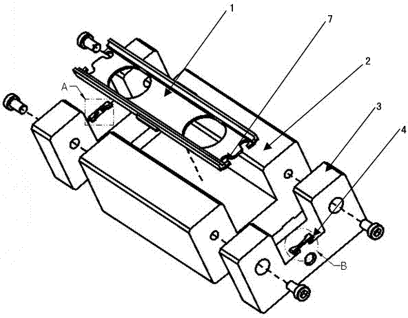
[0025] The linear guide rail slider of the present invention includes an end cover 3, a sliding seat 2, and an internal sealing sheet 1. The end cover 3 is arranged at both ends of the sliding seat 2, and the internal sealing sheet 1 is arranged between the two end covers 3 on the sliding seat 2. On the inner side of the end cover 3, a card 4 with an interference fit between the opening shape and the end of the inner sealing sheet 1 and parallel to the sliding seat 2 is provided on the end cover 3. The card 4 is fixed on the end cover 3 through a support body 5, and the two end cover cards The distance between the 4 openings is slightly less than the length of the internal sealing sheet 1. A slope is provided on the edge of the opening of the card 4 . The distance between the card 4 and the inner side of the sliding seat 2 is matched with the thickness of the inner sealing sheet 1, and the edges of the inner sealing sheet 1 on both sides of the support body 5 are provided with...


PUM


Abstract

The invention relates to a linear guide rail, and in particular relates to an internal sealing piece for the linear guide rail and a linear guide rail sliding block. The invention aims at providing a fixing structure of the internal sealing piece of the linear guide rail sliding block. After the fixing structure is combined with the internal sealing piece, the aim of convenient and rapid assembly can be achieved. The linear guide rail sliding block comprises end covers, a sliding seat and the internal sealing piece, wherein the end covers are respectively arranged at the two ends of the sliding seat; the internal sealing piece is arranged on the inner side of the sliding seat between the two end covers; each end cover is provided with a blocking piece, an opening of the blocking piece is in interference fit with the end of the internal sealing piece, and the blocking piece is parallel to the sliding seat; the blocking pieces are fixed on the end covers by support bodies; the distance between the openings of the blocking pieces of the two end covers is slightly smaller than the length of the internal sealing piece; bulges are respectively arranged at the two sides of each support body at the parts corresponding to the edge of the internal sealing piece; the edge of the internal sealing piece is provided with U-shaped grooves matched with the bulges. The distances between the blocking pieces and the inner side of the sliding seat are matched with the thickness of the internal sealing piece, so that the internal sealing piece is more firmly fixed and does not have shaking phenomenon.

Description

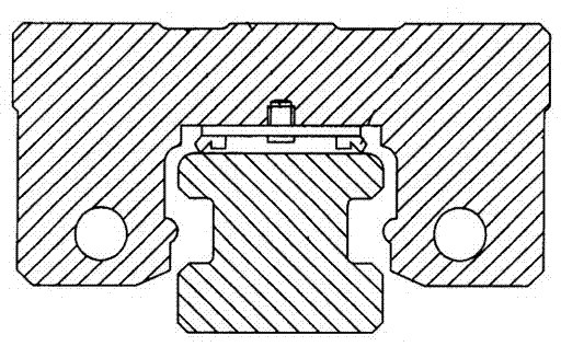
[0001] technical field [0002] The invention relates to a linear guide rail, in particular to an internal sealing sheet for a linear guide rail and a linear guide rail slider. Background technique [0003] In the prior art, the first commonly used form is as figure 1 The U.S. Patent No. US4918846 shown in the invention has a U-shaped internal sealing sheet fixed on the inner top surface of the sliding seat. The locking method between the internal sealing sheet and the sliding seat is divided into two parts. The first part is on the inner top surface of the sliding seat. Drill screw holes and lock them with screws through the screw holes in the middle of the inner sealing sheet. The second part is to lock with the oil nozzle at the end surface of the sliding seat; the aforementioned existing products are affected by the following reasons and are not practical. (like figure 1 shown) [0004] One, the manufacturing procedure of the above-mentioned commonly used prior art i...

Claims


Application Information

Patent Timeline
Patent Type & Authority Applications(China)
IPC IPC(8): F16C29/02F16C33/02F16C33/74
Inventor 廖晏颐张国荣
Owner 青岛祥银传动设备有限公司
Learn More