A road roller transmission

A technology for transmissions and road rollers, applied in the direction of vehicle gearboxes, mechanical equipment, gear transmissions, etc., can solve the problems of forward transformation and speed control without synchronizers, the weight of the assembly is heavy, and the structure is complicated, and the structure is compact and the number of parts Few, easy to manipulate effects

Inactive Publication Date: 2016-02-10
WUHAN ZHONGJUN AUTO PARTS
View PDF6 Cites 0 Cited by
  • Summary
  • Abstract
  • Description
  • Claims
  • Application Information

AI Technical Summary

Problems solved by technology

[0002] At present, the general transmissions of mechanical road rollers with traditional domestic structures in the prior art generally have two structures. In the first structure, the transmission is a forward 3-speed transmission and a reverse 2-speed transmission. All forward gears and reverse gears are arranged on one axis. The gears are arranged sequentially, and the reverse gear is arranged at the rear end of the transmission. The increase of forward and reverse gears in this structure can only be realized by increasing the transmission gear pair, especially the reverse gear requires 2 additional gears for each gear. Secondary, the cost is high, the weight of the assembly is heavy, and every forward and backward operation must be operated sequentially after gear selection and neutral gear, and the operation is complicated; the second structure adopts the combined structure of the reversing box and the speed box, but both The transmission is carried out by installing a transmission shaft in the middle of two independent assemblies, and there is no synchronizer for forward conversion and speed control, the structure is complex and the cost is high

Method used


Image

  • A road roller transmission

Examples


Embodiment Construction

[0012] The technical solutions of the present invention will be clearly and completely described below in conjunction with the accompanying drawings of the present invention. Obviously, the described embodiment is only one embodiment of the present invention, not all embodiments. Based on the embodiments of the present invention, all other embodiments obtained by persons of ordinary skill in the art without creative efforts fall within the protection scope of the present invention.

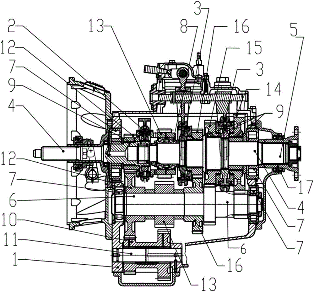
[0013] according to figure 1 As shown, the present invention provides a road roller transmission, including a reversing synchronizer placed inside the casing, a speed change synchronizer, an input shaft, an output shaft, an intermediate shaft, a short cylindrical bearing, a tapered roller bearing, a needle bearing, an inverted Gear idler, reverse idler shaft, reversing gear set, variable speed gear set consisting of pairs of gears with different transmission ratios, output flange, reversing gear s...


PUM


Abstract

The invention provides a transmission of a road roller. The transmission comprises a reversing synchronizer arranged, a speed variable synchronizer, an input shaft, an output shaft, an intermediate shaft, a short cylindrical bearing, a tapered roller bearing, a needle roller bearing, a reverse idler gear, a reverse idler gear shaft, a reversing gear set, a speed variable gear set composed of paired gears with different transmission ratios, and an output flange, wherein the speed variable synchronizer, the input shaft, the output shaft, the intermediate shaft, the short cylindrical bearing, the tapered roller bearing, the needle roller bearing, the reverse idler gear, the reverse idler gear shaft, the reversing gear set, the speed variable gear set composed of the paired gears with the different transmission ratios, and the output flange are arranged in a shell. According to the transmission of the road roller, the manipulation of the change of the forward gear position and the reverse gear position is easy, operation is clear, and gear shifting is easy and convenient; the number of the gears of the transmission of the road roller is increased compared with a transmission of a traditional structure, three forward gears are provided, and three reverse gears are provided; gears can be increased and extended conveniently, the structure is more compact, the number of the parts is less than that of parts of the transmission of the traditional structure, and the cost is further lowered; interchangeability is good, the size and the installing method of the transmission of the road roller are completely the same as those of the transmission of the traditional structure, and upgrading and updating of the transmission with the low cost are facilitated.

Description

technical field [0001] The invention relates to the technical field of transmissions, in particular to a mechanical transmission used in a road roller. Background technique [0002] At present, the general transmissions of mechanical road rollers with traditional domestic structures in the prior art generally have two structures. In the first structure, the transmission is a forward 3-speed transmission and a reverse 2-speed transmission. All forward gears and reverse gears are arranged on one axis. The gears are arranged sequentially, and the reverse gear is arranged at the rear end of the transmission. The increase of forward and reverse gears in this structure can only be realized by increasing the transmission gear pair, especially the reverse gear requires 2 additional gears for each gear. Secondary, the cost is high, the weight of the assembly is heavy, and every forward and backward operation must be operated sequentially after gear selection and neutral gear, and the...

Claims


Application Information

Patent Timeline
Patent Type & Authority Patents(China)
IPC IPC(8): F16H3/12F16H3/093
CPCF16H3/093F16H3/12F16H2200/0043F16H2200/0095
Inventor 关建成张益民
Owner WUHAN ZHONGJUN AUTO PARTS
Why Eureka
Try Eureka