
Geometric error screw theory modeling method for numerically-controlled machine tool

A technology of geometric error and modeling method, which is applied in the field of CNC machine tools and can solve the problem of inability to directly obtain the unified display and expression of the six-dimensional pose error of the machine tool.

Inactive Publication Date: 2014-03-05
TIANJIN UNIV
View PDF4 Cites 18 Cited by
  • Summary
  • Abstract
  • Description
  • Claims
  • Application Information

AI Technical Summary

Problems solved by technology

The method of homogeneous coordinate transformation matrix is ​​the most commonly used modeling tool, but this modeling method cannot directly obtain the unified display expression of the six-dimensional pose error of the machine tool

Method used


Image

  • Geometric error screw theory modeling method for numerically-controlled machine tool
  • Geometric error screw theory modeling method for numerically-controlled machine tool
  • Geometric error screw theory modeling method for numerically-controlled machine tool

Examples


Embodiment Construction

[0030] The specific implementation manner of the present invention will be further described in detail below in conjunction with the accompanying drawings and examples.

[0031] Step 1. Establish the geometric error model of the machine tool kinematic chain

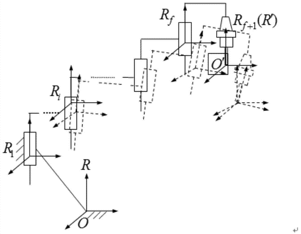
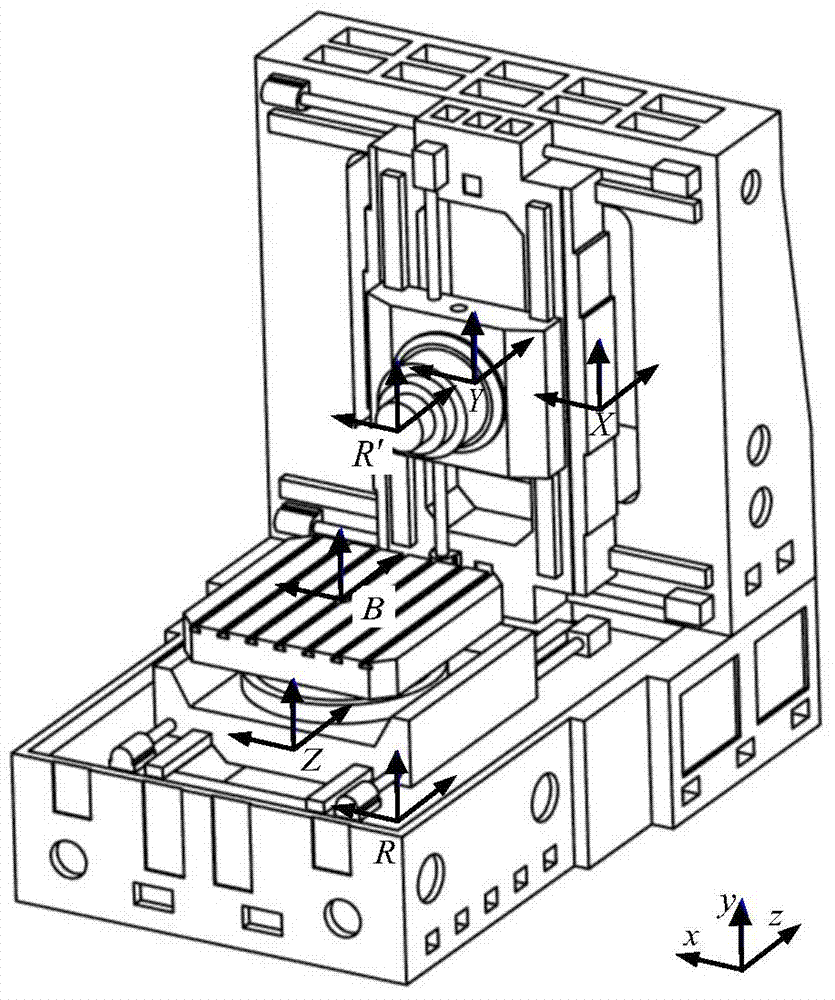
[0032] Such as figure 1 As shown, the global coordinate system R is established at any point O of the bed, and the instantaneous reference coordinate system R' is established at the reference point O' at the end of the kinematic chain, and R' is always parallel to R. In order to describe the effect of each geometric error source in the kinematic chain on the pose error of the end member of the kinematic chain, a conjoined coordinate system R is established on the i-th kinematic pair reference point i . At the same time, a conjoined coordinate system R is established at O' f+1 , and the kinematic chain is in the initial state when R f+1 Consistent with the R' direction.

[0033] According to the structural characteris...


PUM


Abstract

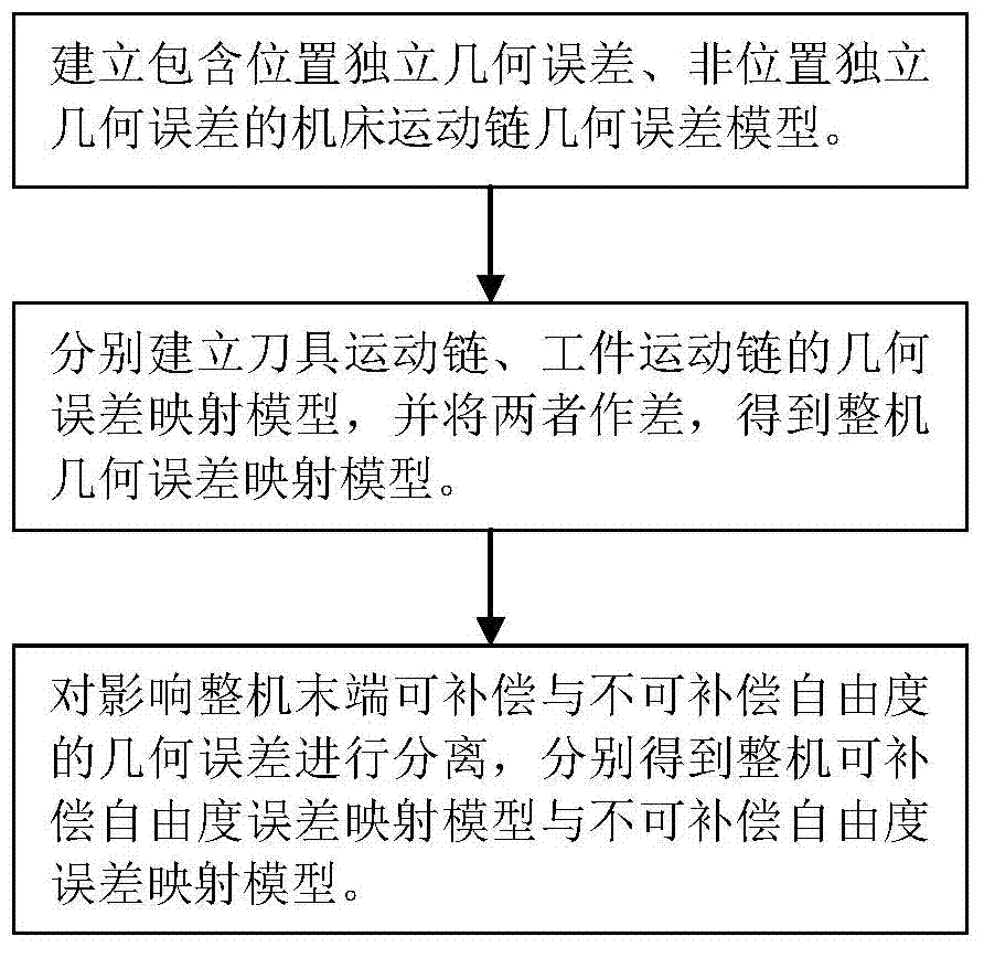
The invention discloses a geometric error screw theory modeling method for a numerically-controlled machine tool. The method includes the first step of establishing an overall coordinate system R at any point on a machine body, establishing instant reference coordinate systems R' at reference points of the tail ends of a kinematic chains and establishing cojoined coordinate systems R[i] on kinematic pairs according to the kinematic chains of the numerically-controlled machine tool, and establishing a machine tool kinematic chain geometric error model containing location independent geometric errors and non-location independent geometric errors, the second step of obtaining a whole machine geometric error mapping model through the machine tool machine tool kinematic chain geometric error modeling method in the first step, and the third step of carrying out separation on compensable freedom degree geometric errors and non-compensable freedom degree geometric errors influencing the tail end of the complete machine according to the properties of a variation space of a restrained rigid body, the properties of a force space of the restrained rigid body, the properties of subspaces of the variation space and the properties of subspaces of the force space to respectively obtain a compensable freedom degree error mapping model and a non-compensable freedom degree error mapping model of the whole machine. Through the method, the mathematical models are provided for error compensation, and an important instructional theoretical basis is provided for error prevention and the precision matching design of the machine tool.

Description

technical field [0001] The invention relates to the technical field of numerical control machine tools, in particular to a modeling method for a general mathematical model of geometric errors of numerical control machine tools. Background technique [0002] There are two main methods for the machining accuracy of CNC machine tools: one is error prevention and the other is error compensation. Error modeling is the key to error compensation. The method of homogeneous coordinate transformation matrix is ​​the most commonly used modeling tool, but this modeling method cannot directly obtain the unified display expression of the six-dimensional pose error of the machine tool. Theoretically, for three-axis, four-axis and five-axis CNC machine tools, only the machine tool pose error corresponding to a given degree of freedom can be compensated through error identification. Therefore, the established error model must be able to effectively separate the geometric error sources that...

Claims


Application Information

Patent Timeline
Patent Type & Authority Applications(China)
IPC IPC(8): G05B19/404
Inventor 田文杰潘琪张大卫常文芬聂应新郭龙真
Owner TIANJIN UNIV
Learn More