
High-sensitivity traveling-wave protection method for high-voltage direct current power transmission line

A traveling wave protection, high-voltage DC technology, applied in emergency protection circuit devices, electrical components, rate of change measurement, etc., can solve the problems of reducing the reliability of protection action, affecting the action time, and lack of engineering applicability.

Active Publication Date: 2014-03-05
EXAMING & EXPERIMENTAL CENT OF ULTRAHIGH VOLTAGE POWER TRANSMISSION COMPANY CHINA SOUTHEN POWER GRID +1
View PDF2 Cites 23 Cited by
  • Summary
  • Abstract
  • Description
  • Claims
  • Application Information

AI Technical Summary

Problems solved by technology

[0004] (1) Increase the communication between converter stations: the actual application of traveling wave protection does not use communication, and the line and system need to be modified, which increases the difficulty of application and reduces the reliability of protection actions; and the existing converter station The communication time is greater than 10ms, which will affect the action time of the protection
[0005] (2) Some studies are more theoretical and lack engineering applicability: the sampling frequency of the new principle of traveling wave protection proposed by some documents is relatively high, up to 1MHz, but the sampling frequency of the current DC system is 6kHz or 10kHz, so a higher sampling frequency is adopted. The sampling frequency of the traveling wave protection principle has limited practical value
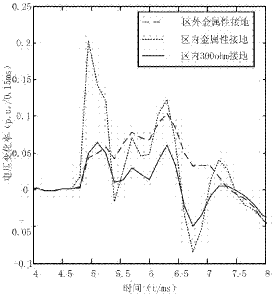
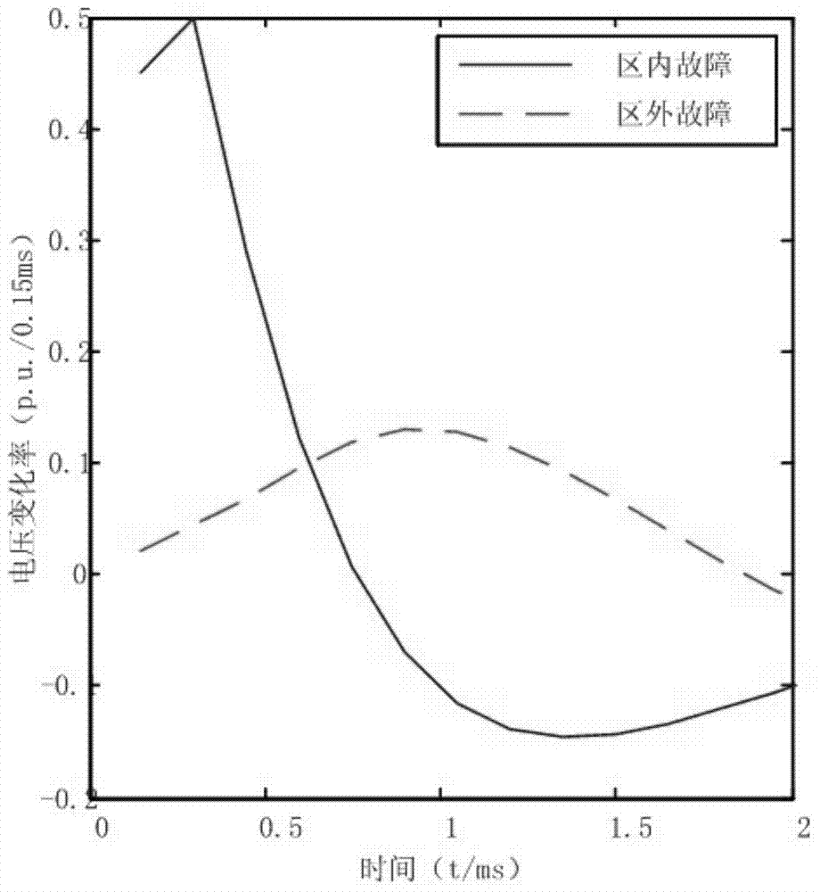
However, this traveling wave protection method only uses the maximum value or extreme value of the voltage change rate, voltage change amount, and current change amount to judge the fault, but this method cannot really distinguish the high-resistance fault inside the zone and the fault outside the zone, and ignores a large number of faults. The transient characteristics of the fault

Method used


Image

  • High-sensitivity traveling-wave protection method for high-voltage direct current power transmission line
  • High-sensitivity traveling-wave protection method for high-voltage direct current power transmission line
  • High-sensitivity traveling-wave protection method for high-voltage direct current power transmission line

Examples


Embodiment Construction

[0052] The present invention will be further described in detail below in conjunction with the embodiments and the accompanying drawings, but the embodiments of the present invention are not limited thereto.

[0053] Such as Figure 5 , a high-sensitivity traveling-wave protection method for HVDC transmission lines, comprising steps in the following order:

[0054] 1) Power on the relay protection device;

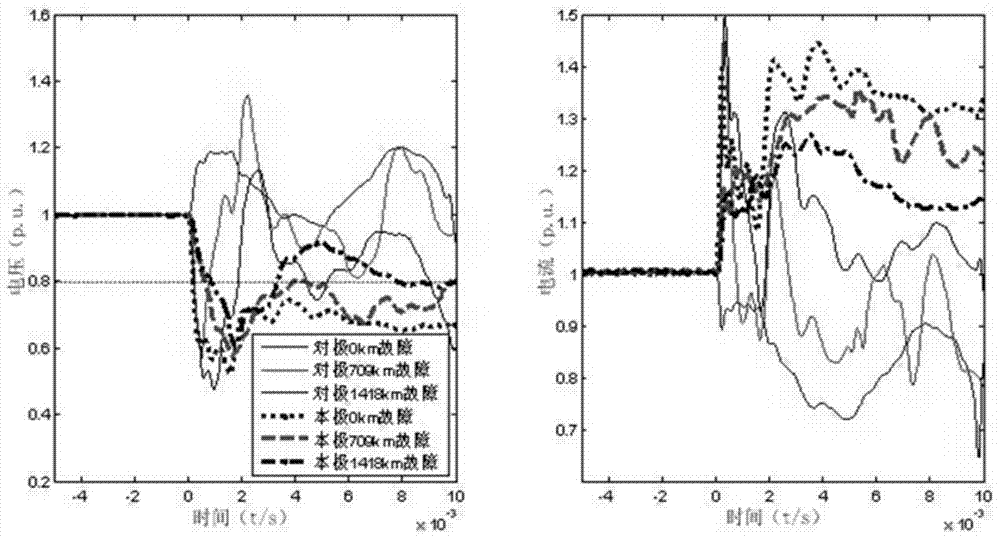
[0055] 2) Assign value to traveling wave protection fixed value Δ initial ,Δ u ,Δ T ,Δ i ,Δ du / dt , where Δ initial is the voltage change rate when the midpoint of the line is grounded with high resistance; Δ u The start and end thresholds for starting to calculate the voltage drop time, Δ u =0.8; Δ T is the protection setting value of the voltage drop time criterion; Δ i Protection setting value of current average value criterion, Δ i =1.05; Δ du / dt is the fixed value of the voltage variation protection criterion;

[0056] The Δ du / dt greater than du / dt at ex...


PUM


Abstract

The invention discloses a high-sensitivity traveling-wave protection method for a high-voltage direct current power transmission line. The method sequentially comprises the steps of powering on a relay protection device; assigning values to traveling-wave protection fixed values Delta initial, Delta u, Delta T, Delta i and Delta du / dt; measuring the voltage u and current i of the line, and calculating a voltage change rate du / dt; judging whether du / dt is greater than Delta initial or not, entering the next step if du / dt is greater than Delta initial, otherwise repeating the step; calculating a voltage change rate calculation value du / dtAVG, an average current change value iAVG and duration T meeting the condition that u is smaller than Delta u; judging whether iAVG at a point is greater than Delta i or not, whether du / dtAVG at the point is greater than Delta du / dt or not and whether T more than or equal to Delta T exists in a time period t1 or not if du / dt is greater than Delta initial, starting protection if the three conditions are met, otherwise continuing judging whether du / dt is greater than Delta initial or not. According to the method, the addition of converter station communication is avoided, and the method is quick in response and high in sensitivity.

Description

technical field [0001] The invention relates to the field of direct current transmission in electric power systems, in particular to a high-sensitivity traveling wave protection method for high-voltage direct current transmission lines. Background technique [0002] In recent years, my country's direct current transmission has developed rapidly, and a large number of direct current transmission projects are about to be put into production or operation. Therefore, direct current transmission will play a vital role in the safety and stability of my country's power grid and the optimal allocation of resources in the future. However, the line protection of existing DC transmission projects has a low correct action rate for line faults, which is concentrated in the fact that the main protection traveling wave protection of the line protection has a low ability to withstand transition resistance, and the ability to withstand transition resistance at weak points is lower than 100 o...

Claims


Application Information

Patent Timeline
IPC IPC(8): H02H7/26G01R19/12
Inventor 冯鸫刘琳郑伟王钢李海锋武霁阳
Owner EXAMING & EXPERIMENTAL CENT OF ULTRAHIGH VOLTAGE POWER TRANSMISSION COMPANY CHINA SOUTHEN POWER GRID
Learn More