Peritoneal dialysis system, device and method

A peritoneal dialysate, peritoneal technology, used in the treatment of advanced renal failure, to solve problems such as imperfect execution, inaccuracy, patient well-being and health impairments

Inactive Publication Date: 2014-03-05
NXSTAGE MEDICAL
View PDF2 Cites 44 Cited by
  • Summary
  • Abstract
  • Description
  • Claims
  • Application Information

AI Technical Summary

Problems solved by technology

Prescriptions may be incorrectly or imperfectly executed due to error, resulting in damage to the well-being and health of the patient

Method used


Image

  • Peritoneal dialysis system, device and method
  • Peritoneal dialysis system, device and method
  • Peritoneal dialysis system, device and method

Examples


Embodiment Construction

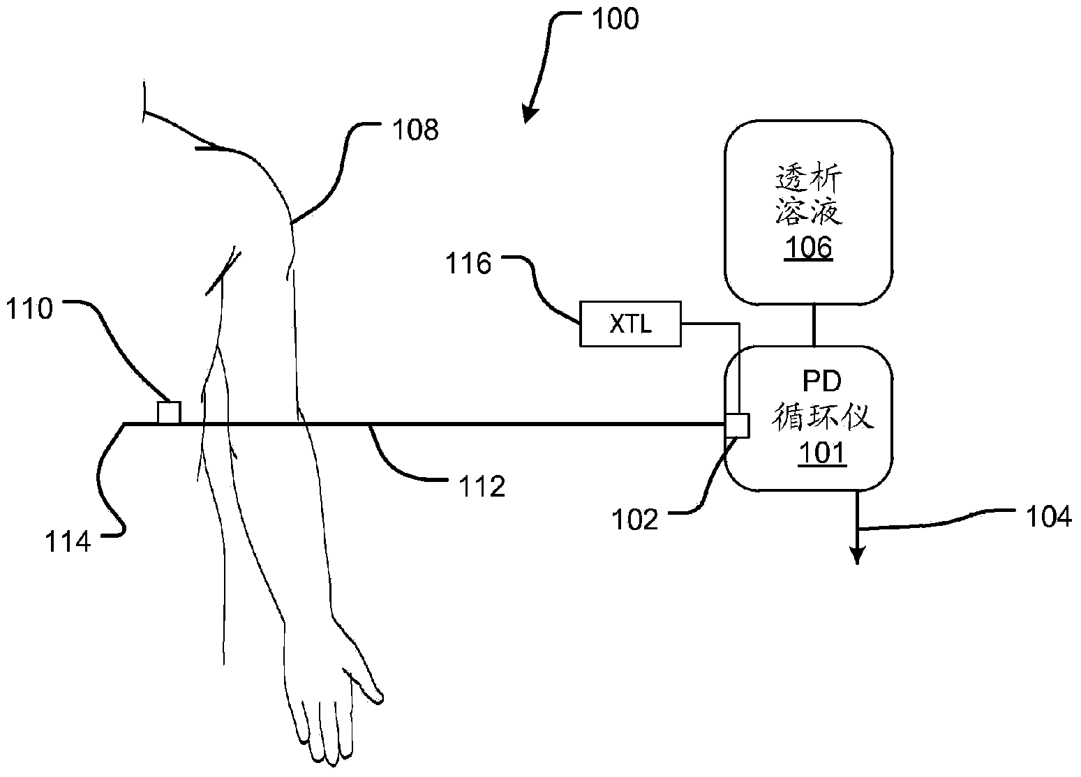
[0046] refer to figure 1 , a peritoneal dialysis system 100 includes a peritoneal dialysis (PD) cycler 101 with an internal pump (not shown). PD cycler 101 pumps dialysis solution from container 106 , such as a bag or other source, through fill / drain line 112 to peritoneal catheter 114 , to patient channel 114 , and into the peritoneum of patient 108 . This happens during the fill cycle.

[0047] During the drain cycle, spent dialysate is recovered by flowing in reverse through the fill / drain line back to the cycler 101 and out through the drain 104 . The cycler 101 quantifies the infused and expelled fluid volumes and provides accounting for the difference to allow determination of the net volume of fluid recovered from the patient.

[0048] The pump may be any suitable pump such as a diaphragm pump or a peristaltic pump. Alternatively, the cycler may rely on other fluid delivery systems such as over or under pressure supply / collection vessels, gravity fed water, or other...


PUM


Abstract

An automated peritoneal dialysis system provides various features. The features includes prescription-driven dialysis fluid preparation, an integrated disposable fluid circuit, and sensor capabilities that allow accurate filing and draining control with high safety margins. The features include a peritoneal fluid circuit with a pressure sensor at either end and methods and devices for using the pressure signals. Other features and embodiments are disclosed.

Description

[0001] Cross References to Related Applications [0002] This application claims priority to US Provisional Applications 61 / 466,921, filed March 23, 2011, 61 / 470,183, filed May 26, 2011, and 61 / 509,240, filed July 19, 2011. Background technique [0003] The subject matter disclosed herein relates generally to the treatment of advanced renal failure, and more specifically to devices, methods, systems, improvements and assemblies for performing peritoneal dialysis. [0004] Peritoneal dialysis is a well-established technique that has been used for many years. It is one of two commonly used forms of dialysis, the other being hemodialysis, which uses artificial membranes to directly purify the blood of people with kidney disease. Peritoneal dialysis uses the natural membrane of the peritoneum to allow excess water and toxins to be removed from the blood. [0005] In peritoneal dialysis, a sterile peritoneal solution is injected into the patient's abdominal cavity using a cathet...

Claims


Application Information

Patent Timeline
Patent Type & Authority Applications(China)
IPC IPC(8): A61M1/28
CPCA61M2001/288A61M2205/12A61M1/28A61M1/288A61M2025/0002A61M2205/3351A61M2205/128A61M2205/3334A61M1/285A61M2205/3355A61M1/1562A61M1/155A61M1/1524A61M1/1565A61M1/159A61M1/154A61M1/1656A61M1/166A61M1/1664A61M1/1668A61M1/167A61M1/1672A61M1/1674A61M1/282A61M1/287A61M2205/14A61M2205/123A61M2205/18A61M2205/3331A61M2205/52A61M2230/005A61M1/281A61M2205/33
Inventor 杰弗里·H·伯班克詹姆斯·M·布鲁格丹尼斯·M·特罗伊马克·T·韦思
Owner NXSTAGE MEDICAL
Why Eureka
Try Eureka