Brake device mounted on flight experience device

A brake device and brake pad technology, which is applied in the field of brake devices, can solve the problems of affecting the safety effect, hidden safety hazards, and long time-consuming locking, and achieve the effects of reasonable structural design, extended service life, and good braking performance

Active Publication Date: 2015-04-01
HUAQIANG FANGTE WUHU CULTURE TECH CO LTD
View PDF6 Cites 0 Cited by
  • Summary
  • Abstract
  • Description
  • Claims
  • Application Information

AI Technical Summary

Problems solved by technology

In some existing large-scale entertainment venues, there are many exciting and thrilling entertainment projects, such as outdoor projects such as roller coasters, which use actual visual impact and physical experience to achieve the purpose of thrilling and thrilling. Although there are many safety protection devices, there are still potential safety hazards
For this reason, people began to design many indoor entertainment projects, using the synchronous action of the indoor video and the equipment that tourists ride, so that tourists have an immersive feeling, and the indoor equipment is also relatively cumbersome, and the inertia when exercising is relatively large. , This brings trouble to the brakes. If the traditional brake device is used, it is often prone to slipping, that is, it cannot be braked, which will cause harm to the life safety of tourists.
[0003] Another example is the Chinese patent ZL200610062119.7, which proposes a motion simulation device, system and method for entertainment. The locking mechanism used includes a connecting frame fixedly connected to the frame, and the middle position is pivotally connected to the upper and lower sides of the connecting frame. The upper link and the lower link, the upper splint installed at one end of the upper link, the lower splint corresponding to the upper splint installed at one end of the lower link, and the other end connected to the upper link and the lower link at the same time Locking oil cylinder, a spring is provided between the upper connecting rod and the connecting frame, and a spring is provided between the lower connecting rod and the connecting frame; the locking oil cylinder pushes the opening and closing of the upper connecting rod and the lower connecting rod, and drives the upper connecting rod The splint and the lower splint are opened and closed to loosen or clamp the upper support surface of the guide rail. This locking method uses the mutual extrusion between the upper splint and the lower splint to clamp the guide rail between the upper splint and the lower splint bracket. , complete the locking, and because the machine itself is relatively bulky and has a large inertia, it is difficult to achieve fast locking with this locking method. It is often only after the machine slides for a small displacement that complete locking can be achieved, and locking takes a long time. long; and there is no special design for the contact parts of the upper splint, the lower splint and the guide rail, but the friction between the planes is used to achieve locking, which is very prone to slipping, that is, if the thrust of the locking cylinder does not reach a certain value, the machine will Sliding along the guide rail can not achieve locking, so the locking lags behind, and there is a locking delay, which makes it difficult to compile the control program, resulting in inconsistent positions for each stop, which affects the entertainment effect

Method used


Image

  • Brake device mounted on flight experience device
  • Brake device mounted on flight experience device
  • Brake device mounted on flight experience device

Examples


Embodiment Construction

[0020] In order to make the technical means, creative features, goals and effects achieved by the present invention easy to understand, the present invention will be further elaborated below.

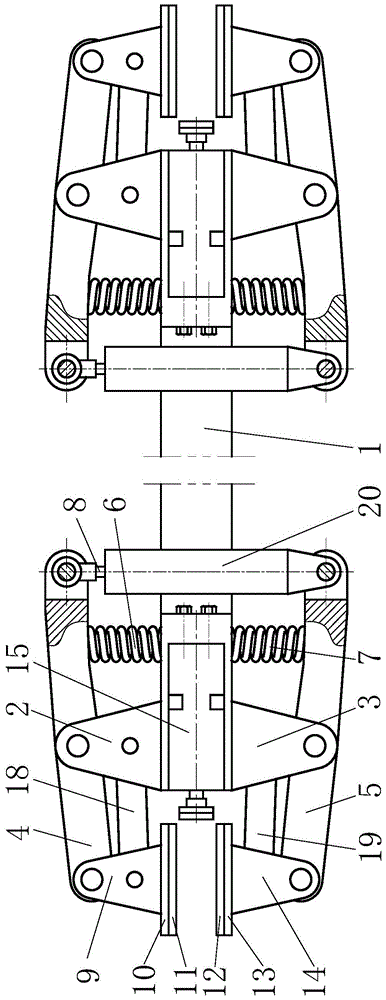
[0021] like Figure 1 to Figure 5 As shown, a brake device installed on a flight experience device includes a support platform 1, and combined brakes are symmetrically installed on the left and right ends of the support platform 1, and the combined brake includes an upper main support 2, The lower main support 3 and the lateral brake, the upper main support 2 and the lower main support 3 are symmetrically installed on the upper and lower sides of the support platform 1, and the upper main support 2 is connected with an upper lever in a hinged manner Beam 4, the left end of the upper lever beam 4 is connected with the upper brake pushing block 9 through a hinged mode, the middle part of the right side of the upper lever beam 4 is connected with the support platform 1 through the upper te...


PUM


Abstract

The invention relates to a brake device mounted on a flight experience device. The brake device mounted on the flight experience device comprises a supporting platform, a combined type brake is symmetrically mounted at the left end and the right end of the supporting platform, and the combined type brake comprises an upper main support, a lower main support and a lateral brake. The lateral brake comprises a lateral shoving and pushing device, a lateral brake shoving and pushing block and a lateral brake cushion. The lateral shoving and pushing device is located between the upper main support and the lower main support, the lateral shoving and pushing device is fixedly connected to a supporting platform, the lateral brake cushion is located between an upper brake cushion and a lower brake cushion, and one side of the lateral brake cushion is connected with the lateral shoving and pushing device through the lateral brake shoving and pushing block. The brake device mounted on the flight experience device has the advantages of being reasonable in structural design, convenient to control, good in brake performance and the like; the occurrence of slipping is avoided by adopting a vertical brake and a transverse brake combining mode and by using the fact that the tooth groove direction of first transverse antiskid zigzag teeth, the tooth groove direction of second transverse antiskid zigzag teeth and the tooth groove direction of vertical antiskid zigzag teeth are all perpendicular to the walking direction of a machine, and rapid braking can be achieved in a flight experience process.

Description

technical field [0001] The invention relates to a brake device, in particular to a brake device installed on a flight experience device. Background technique [0002] With the improvement of people's living standards, people's pursuit of entertainment life is becoming more and more enthusiastic, especially young people, most of them pursue some exciting and thrilling entertainment activities, which is also an adjustment to the daily high-pressure and high-load work status. , so as to ensure a positive and optimistic working attitude at work. In some existing large-scale entertainment venues, there are many exciting and thrilling entertainment projects, such as outdoor projects such as roller coasters, which use actual visual impact and physical experience to achieve the purpose of thrilling and thrilling. Although there are many safety protection devices, there are still potential safety hazards. For this reason, people began to design many indoor entertainment projects, u...

Claims


Application Information

Patent Timeline
Patent Type & Authority Patents(China)
IPC IPC(8): A63G31/00
Inventor 陈祖尧易伟林
Owner HUAQIANG FANGTE WUHU CULTURE TECH CO LTD
Why Eureka
Try Eureka