Sleeve uninstalling device

A technology for unloading sleeves and hydraulic cylinders is applied in the field of unloading sleeve devices, which can solve the problems of sleeve inclination and cumbersomeness, and achieve the effects of balanced force, improved productivity, and saving time and human resources.

Inactive Publication Date: 2014-03-12
CHINA NAT HEAVY MACHINERY RES INSTCO
View PDF7 Cites 5 Cited by
  • Summary
  • Abstract
  • Description
  • Claims
  • Application Information

AI Technical Summary

Problems solved by technology

[0002] Sleeves are used in various metal strip finishing units (such as continuous annealing, galvanizing, and recoiling units). In strip processing units, the sleeves are relatively heavy. It is cumbersome to lift the sleeve away from the unloading trolley; while other forms, such as a single head mechanism, tend to tilt the sleeve when unloading the sleeve

Method used


Image

  • Sleeve uninstalling device
  • Sleeve uninstalling device

Examples


Embodiment Construction

[0013] The invention relates to the technical field of finishing equipment for metal strips, in particular to a sleeve unloading device.

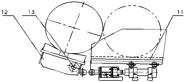
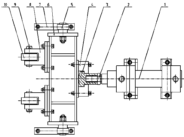
[0014] see figure 1 and figure 2 Shown, the concrete structure of a kind of unloading sleeve device that the present invention relates to is:

[0015] Including hydraulic cylinder 1, oil cylinder joint 3, clamping plate 4, first wheel 5, frame body 6, track 7, support 8, second wheel 10, collection basket 11 and trolley bracket 12; among them,

[0016] The hydraulic cylinder 1 is fixed, the hydraulic cylinder 1 is connected with the clamp 4 through the cylinder joint 3, the clamp 4 is further connected with the frame body 6, and the frame body 6 is connected with the support 8 again,

[0017] The first wheel 5 is arranged on both sides of the frame body 6, and the lower end of the first wheel 5 is provided with a track 7. During work, the first wheel 5 rolls on the track 7, and the second wheel 10 is installed on the support 8.

[0018]...


PUM


Abstract

The invention relates to a sleeve uninstalling device which is characterized by comprising a hydraulic cylinder, an oil cylinder joint, a clamp plate, first wheels, a frame body, rails, a pedestal, a second wheel, a collecting basket and a trolley bracket, wherein the hydraulic cylinder is fixed, the hydraulic cylinder is connected with the clamp plate through the oil cylinder joint, then the clamp plate is connected with the frame body, the frame body is connected with the pedestal, the first wheels are arranged on both sides of the frame body, the lower ends of the first wheels are provided with the rails, the second wheel is arranged on the pedestal, the collecting basket is arranged on a stand above the hydraulic cylinder, the hydraulic cylinder is arranged on a base plate of the stand, the trolley bracket is fixed on the frame body through a hinge pin, and runs perpendicular to a plane on which the collecting basket is located. The sleeve uninstalling device disclosed by the invention can store sleeves, so that sleeves are not required to be lifted away one by one every time. By using the sleeve uninstalling device disclosed by the invention, sleeves can be stored together, and then are integrally lifted away, so that time and manpower resources are saved, and the productivity of units is improved.

Description

technical field [0001] The invention relates to a sleeve unloading device. Background technique [0002] Sleeves are used in various metal strip finishing units (such as continuous annealing, galvanizing, and recoiling units). In strip processing units, the sleeves are relatively heavy. It is cumbersome to hang the sleeve from the unloading trolley; while other forms, such as a single head mechanism, tend to tilt the sleeve when unloading the sleeve. Contents of the invention [0003] The technical problem to be solved by the present invention is to provide a sleeve unloading device to overcome the defects in the prior art. A novel sleeve unloading device with simple structure, strong practicability and easy implementation is provided. [0004] The technical solution of the present invention is: A sleeve unloading device, characterized in that it includes a hydraulic cylinder, an oil cylinder joint, a clamp, a first wheel, a frame body, a track, a support, a second wheel...

Claims


Application Information

Patent Timeline
Patent Type & Authority Applications(China)
IPC IPC(8): B21C47/24
Inventor 高聪敏刘忠宝吴永杰任玉成常瑜靳恩辉徐长安
Owner CHINA NAT HEAVY MACHINERY RES INSTCO
Why Eureka
Try Eureka