Wire welding machine

A wire welding machine and wire welding technology, applied in the field of wire welding machines, can solve the problems of large load and low welding precision of the welding head, and achieve the effects of large load, improved welding precision and avoiding the increase of load

Active Publication Date: 2014-03-12
AE AUTOMATION & ROBOTICS TECH LTD
View PDF6 Cites 2 Cited by
  • Summary
  • Abstract
  • Description
  • Claims
  • Application Information

AI Technical Summary

Problems solved by technology

[0004] The invention provides a wire welding machine, which can solve the problems of the prior art that the welding head of the wire welding machine has a large load when it moves axially and the welding head has low wire welding accuracy

Method used


Image

  • Wire welding machine
  • Wire welding machine
  • Wire welding machine

Examples


Embodiment Construction

[0023] The following will clearly and completely describe the technical solutions in the embodiments of the present invention with reference to the accompanying drawings in the embodiments of the present invention. Obviously, the described embodiments are only some, not all, embodiments of the present invention. Based on the embodiments of the present invention, all other embodiments obtained by persons of ordinary skill in the art without making creative efforts belong to the protection scope of the present invention.

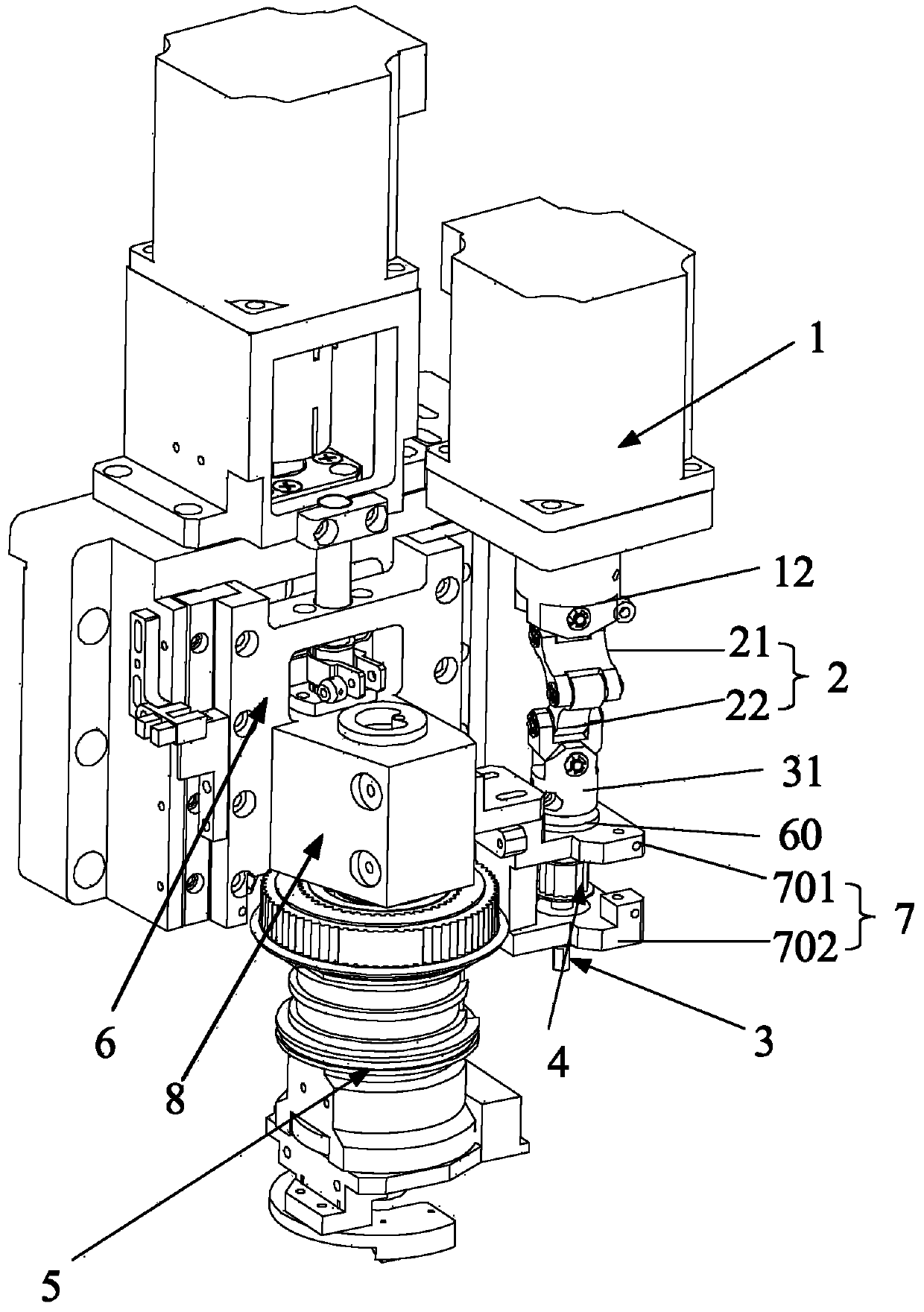
[0024] see figure 1 , figure 1 It is a partial three-dimensional structure schematic diagram of an embodiment of the wire bonding machine of the present invention. The wire bonding machine includes but is not limited to a rotary drive device 1, a flexible transmission device 2, a transmission shaft 3, a transmission device 4, a welding head 5, an axial drive device 6, and a connecting device 7. The rotary drive device 1 drives the flexible transmission device...


PUM


Abstract

The embodiment of the invention provides a wire welding machine. The wire welding machine comprises an axial driving device, a welding head, a rotation driving device, a flexible transmission device and a connecting device. The welding head is connected with the axial driving device; the flexible transmission device is connected with the rotation driving device; the connecting device is fixedly connected with the welding head and the flexible transmission device; the rotation driving device drives the flexible transmission device to rotate, and the axial driving device drives the flexible transmission device to carry out telescopic movement when driving the welding head to move in the axial direction of the welding head. In this way, loads can be prevented from increasing when the wire welding machine moves axially, and the wire welding precision of the welding head is improved.

Description

technical field [0001] The invention relates to the field of welding technology, in particular to a wire welding machine. Background technique [0002] Wire bonding machines include gold wire machines, aluminum wire machines, ultrasonic wire bonding machines, etc. The wire bonding machine is mainly used in high-power devices: light-emitting diodes, laser tubes, small and medium-sized power triodes, integrated circuits and inner lead welding of some special semiconductor devices. [0003] During the wire welding process, the wire bonding machine needs to continuously adjust the direction of the wire, that is, the welding head needs to be rotated to ensure the smooth progress of the wire welding process. In the prior art, the welding head rotation is realized by the drive device transmitting torque through a rigid shaft. However, this way of transmitting torque makes the distance between the driving device and the welding head relatively fixed. When the welding head needs to ...

Claims


Application Information

Patent Timeline
IPC IPC(8): B21F15/08B23K37/02
Inventor 刘晔东李晓光
Owner AE AUTOMATION & ROBOTICS TECH LTD
Why Eureka
Try Eureka