Welding head moving device and wire welding machine

The technology of a motion device and a wire bonding machine is applied in the field of wire bonding machines, which can solve the problems of increasing the rotational inertia of the Z axis, difficult to improve the rotational acceleration, and low wire welding accuracy of the wire bonding machine, so as to reduce the rotational inertia and improve the wire welding accuracy. , the effect of reducing the overall weight

Pending Publication Date: 2021-05-04
GKG PRECISION MACHINE
View PDF1 Cites 3 Cited by
  • Summary
  • Abstract
  • Description
  • Claims
  • Application Information

AI Technical Summary

Problems solved by technology

[0005] 1. The center of gravity of the welding head movement device is biased towards the side of the clamp of the wire welding machine, which causes the center of gravity of the head structure (including the head frame, transducer and wire clamp of the welding machine) rotating on the Z axis to deviate from its rotation center, so that The state head structure is not stable enough when rotating, the rotation acceleration is difficult to increase, and the wire bonding accuracy of the wire bonding machine is not high;
[0006] 2. In order to overcome the problem that the head structure is not stable enough when it rotates, the existing technology increases the weight of the transducer or the head frame so that the center of gravity of the head structure is as close as possible to its center of rotation; but this setting will increase the weight of the head structure. The weight increases the rotational inertia on the Z axis, making it difficult to increase the rotational acceleration, and the wire welding accuracy of the wire bonding machine is not high

Method used


Image

  • Welding head moving device and wire welding machine
  • Welding head moving device and wire welding machine
  • Welding head moving device and wire welding machine

Examples


Embodiment Construction

[0045] In order to make the purpose, features and advantages of the present invention more obvious and understandable, the technical solutions in the embodiments of the present invention will be clearly and completely described below in conjunction with the accompanying drawings in the embodiments of the present invention. Obviously, the following description The embodiments are only some of the embodiments of the present invention, but not all of them. Based on the embodiments of the present invention, all other embodiments obtained by persons of ordinary skill in the art without making creative efforts belong to the protection scope of the present invention.

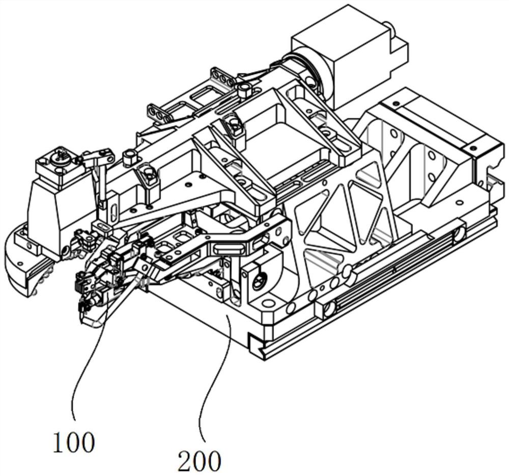
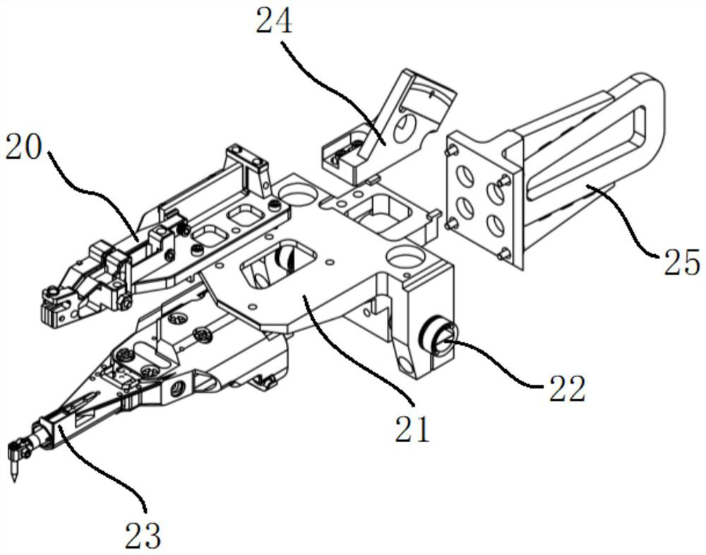
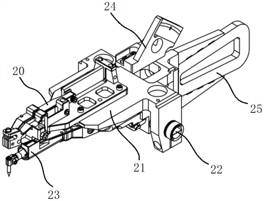
[0046] see Figure 1 to Figure 5 As shown, this embodiment provides a welding head moving device, which includes a bond head base 200 and a bond head structure 100 hinged to the bond head base 200 . When in use, the bond head structure 100 swings vertically on the Z axis.

[0047] Specifically, in the welding head mo...


PUM


Abstract

The invention discloses a welding head moving device and a wire welding machine. The welding head moving device comprises a bonding head structure, wherein the bonding head structure comprises a bonding head frame hinged to a welding head base body, and a wire welding machine wire clamp and an invar transducer which are respectively fixed onto the bonding head frame; the wire welding machine wire clamp adopts a piezoelectric ceramic element as a driving source; and the gravity center of the bonding head structure coincides with or approximately coincides with the rotation center. As the bonding head structure uses the invar transducer with lighter weight and the wire welding machine wire clamp with lighter weight, the overall weight of the bonding head structure can be reduced, and the rotation inertia of the Z axis is reduced; and the gravity center of the bonding head structure can be set to coincide with or approximately coincide with the rotation center as much as possible, so that the stability of the bonding head structure during rotation is improved, the acceleration of the bonding head structure can be improved finally, and the wire welding precision of the wire welding machine is improved.

Description

technical field [0001] The invention belongs to the technical field of wire welding machines, and in particular relates to a welding head movement device and a wire welding machine. Background technique [0002] The Chinese invention patent whose publication number is CN107127447A discloses a wire bonding machine and a welding head moving device thereof. The welding head movement device is used as the Z axis of the wire bonding machine in the wire bonding of the wire bonding machine, and forms a three-axis linkage with the X and Y axes to make wire arcs with different trajectories. In the wire bonding process, the wire is used for electrode connection between the pads of electronic components. The wire is a gold wire, silver wire, copper wire, copper-palladium wire or alloy wire with a diameter of 17um-33um, and the Z-axis direction is rotational movement. Among them, a pair of flexible fulcrums are connected to the base body of the head and the head frame. The flexible ful...

Claims


Application Information

Patent Timeline
Patent Type & Authority Applications(China)
IPC IPC(8): B23K37/00B23K37/02B21F15/10H01R43/02
CPCB21F15/10B23K37/00B23K37/0247B23K37/0252H01R43/02
Inventor 邱国良宋先玖陈土军
Owner GKG PRECISION MACHINE
Why Eureka
Try Eureka