
Workpiece positioning tool for machine tool

A technology for positioning tooling and lathes, which is applied in the field of lathes and can solve the problems of inability to meet the processing requirements of the coaxiality of workpieces, high coaxiality, and inability to guarantee the processing of circular surfaces and positioning circular surfaces.

Active Publication Date: 2014-03-12
SHANTUI CONSTR MASCH CO LTD
View PDF5 Cites 2 Cited by
  • Summary
  • Abstract
  • Description
  • Claims
  • Application Information

AI Technical Summary

Problems solved by technology

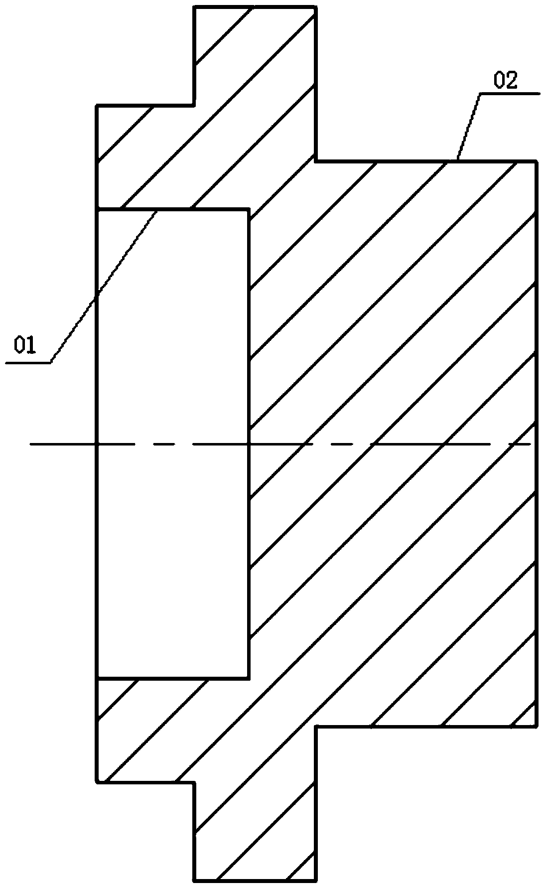
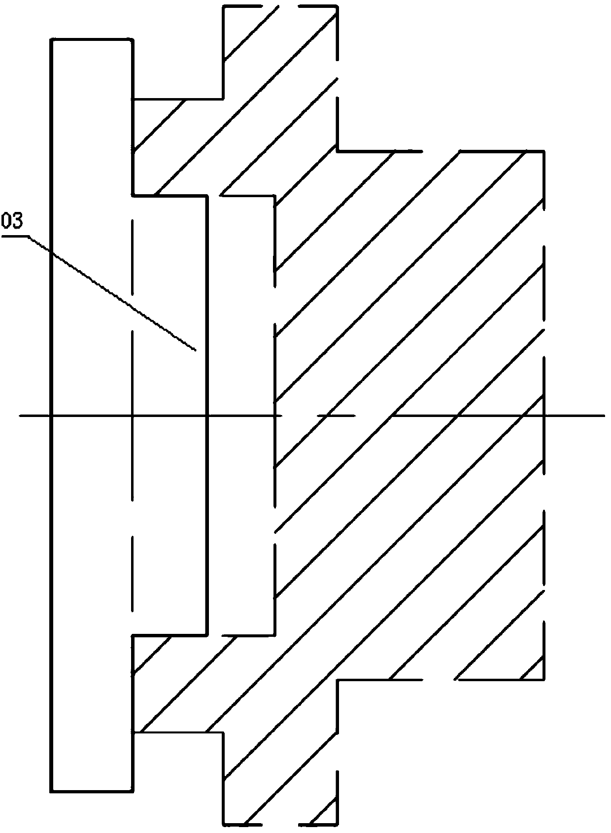
Considering the manufacturing error, the use of the mandrel tool does not guarantee a high degree of coaxiality between the machining circular surface and the positioning circular surface
The coaxiality requirement that this type of tooling can guarantee is up to 0.03mm, which cannot meet the processing requirements of the workpiece for coaxiality

Method used


Image

  • Workpiece positioning tool for machine tool
  • Workpiece positioning tool for machine tool
  • Workpiece positioning tool for machine tool

Examples


Embodiment Construction

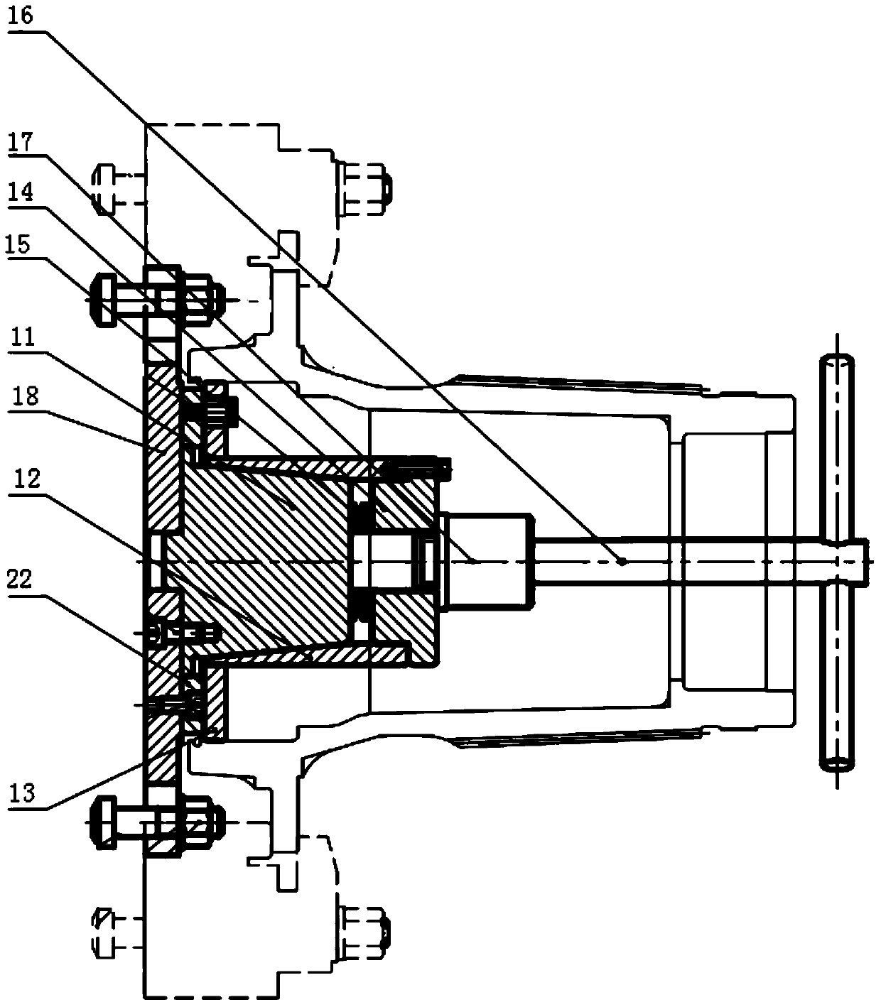
[0035] This embodiment provides a workpiece positioning tool for a lathe, which can ensure that the circular surfaces at different positions have high coaxiality when processing round surfaces at different positions.

[0036] The technical solutions in the embodiments of the present invention will be clearly and completely described below in conjunction with the accompanying drawings in the embodiments of the present invention. Obviously, the described embodiments are only a part of the embodiments of the present invention, rather than all the embodiments. Based on the embodiments of the present invention, all other embodiments obtained by those of ordinary skill in the art without creative work shall fall within the protection scope of the present invention.

[0037] Please refer to Figure 3-Figure 5 , A workpiece positioning tool for a lathe provided by this embodiment includes:

[0038] The cone 11 includes a first end surface and a second end surface, and the cross-sectional ar...


PUM


Abstract

The invention discloses a workpiece positioning tool for a machine tool. The workpiece positioning tool for the machine tool comprises a cone, an inner cone sleeve, an elastic positioning ring, a gland, an elastic part, a rotation handle and a base. The cone comprises a first end face and a second end face, and the cross section area of the cone is gradually enlarged in the direction from the first end face to the second end face. The inner cone sleeve is arranged on the periphery of the cone in a sleeved mode. The elastic positioning ring is arranged on the periphery of the inner cone sleeve in a sleeved mode. The gland abuts against the end, close to the first end face of the cone, of the inner cone sleeve. The elastic part is connected between the gland and the cone in an abutted mode. The base is connected with the machine tool and connected with the second end face of the cone. With the arrangement, the high coaxiality of round faces at different positions can be ensured when the round faces at the different positions are machined with the workpiece positioning tool for the machine tool.

Description

Technical field [0001] The invention relates to the technical field of lathes, in particular to a workpiece positioning tool for lathes. Background technique [0002] During the machining process of the lathe, the workpiece needs to be fixed on the worktable of the lathe first. The worktable rotates to drive the workpiece to move together. The tool is fixed on the tool holder. During processing, the tool holder is controlled to realize the contact between the tool and the workpiece. The relative movement realizes the cutting function. Due to the rotating motion of the worktable, most of its processed surfaces are round surfaces, such as shafts, holes, cones, etc. [0003] The processing requirements of many workpieces are multiple shafts, holes, etc., and the process requires high coaxiality. For this kind of parts, the workpiece needs to be clamped once to complete multiple holes or shafts with high coaxiality requirements. Surface processing. [0004] However, if the two circula...

Claims


Application Information

Patent Timeline
Patent Type & Authority Applications(China)
IPC IPC(8): B23B31/40
CPCB23B31/4006B23B31/4013
Inventor 吕海波武永福权中华李涛涛魏晓蓓刘兰兰刘坤姜立勇胡传朋
Owner SHANTUI CONSTR MASCH CO LTD
Learn More