Glue injection and compaction fixture

A tooling and glue injection technology, applied in the direction of workpiece clamping devices, manufacturing tools, hand-held tools, etc., can solve problems such as unqualified, uneven upper and lower flanges, expansion, etc., and achieve convenient operation, simple structure, and high glue injection quality Good results

Inactive Publication Date: 2014-03-12
山东彼岸电力科技有限公司
View PDF5 Cites 6 Cited by
  • Summary
  • Abstract
  • Description
  • Claims
  • Application Information

AI Technical Summary

Problems solved by technology

The existing glue injection process is often unqualified because the upper and lower flanges are not level, the upper and lower flange holes are not aligned, and the glue expands after injection, etc.

Method used


Image

  • Glue injection and compaction fixture
  • Glue injection and compaction fixture
  • Glue injection and compaction fixture

Examples


Embodiment Construction

[0014] The present invention will be specifically described below in conjunction with the accompanying drawings and embodiments.

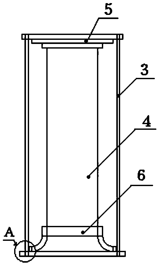
[0015] figure 1 Shown is the structural representation of the present invention.

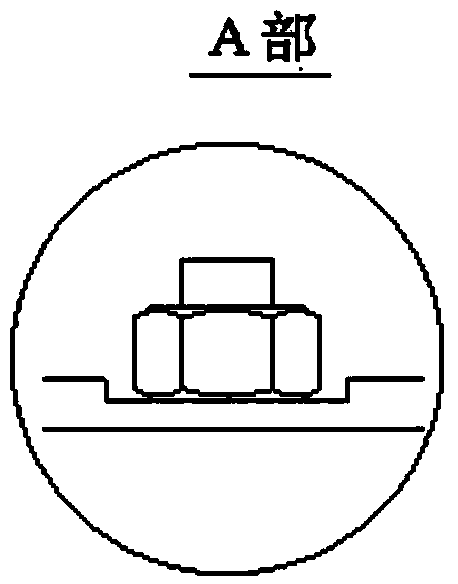
[0016] figure 2 shown as the present invention figure 1 The enlarged schematic diagram of part A.

[0017] The present invention includes an epoxy pipe 4, an upper flange 5 and a lower flange 7, an upper pressing plate 1, a lower pressing plate 2, a pull rod 3 and a base 6.

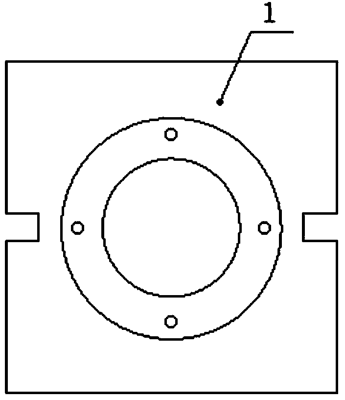
[0018] image 3 Shown is a schematic structural view of the upper platen of the present invention.

[0019] The upper platen 1 is a square structure with a screw hole in the middle and a groove on both sides. The upper flange 5 is fixed on the lower plane of the upper platen 1 by bolts.

[0020] Figure 4 Shown is a structural schematic diagram of the lower pressing plate of the present invention.

[0021] The lower platen 2 is a square structure, the middle part is provided with a base...


PUM


Abstract

The invention discloses a glue injection and compaction fixture which comprises an epoxy pipe, an upper flange and a lower flange, and further comprises an upper compaction plate, a lower compaction plate, pull rods and a base, wherein the upper compaction plate is of a square structure, a threaded hole is formed in the middle of the upper compaction plate, a groove is formed in each of two sides of the upper compaction plate, the upper flange is fixed on the lower plane of the upper compaction plate through bolts, the lower compaction plate is of a square structure, a base installing hole is formed in the middle of the lower compaction plate, grooves corresponding to the upper compaction plate are formed in two sides of the lower compaction plate, the base is fixed on an upper plane of the lower compaction plate through a bolt, the lower flange is positioned on the base, the epoxy pipe is arranged between the upper compaction plate and the lower compaction plate, and the pull rods are respectively arranged in the grooves in two sides and fixed by using regulating nuts. According to the glue injection and compaction fixture, the flanges are compacted by using the upper horizontal compaction plate and the lower horizontal compaction plate, are forced to keep horizontal, and then are tensioned by using the pull rods and the bolts, thus the total length of the glue injection and compaction fixture is controlled and no deformation of the glue injection and compaction fixture is kept in a glue injection process. The glue injection and compaction fixture has the advantages of simple structure, convenience in operation, and good glue injection quality.

Description

technical field [0001] The invention relates to a glue injection compacting tool, in particular to a glue injection compaction technology for flanges at both ends of an epoxy pipe. Background technique [0002] In the production of various types of high-voltage transformers, the bushing is a very important part and plays an important role in the transformer. Among them, epoxy tube glue injection is the first and most important step in the bushing production process. , The epoxy pipe glue injection process is to install and fix the upper and lower flanges on the epoxy pipe. It is required that the upper and lower flanges must be horizontal, the screw holes of the upper and lower flanges are aligned, the total length of the epoxy pipe is within the control tolerance, and the flange and epoxy The gap between the tubes is even. The existing glue injection process is often unqualified because the upper and lower flanges are not level, the upper and lower flange holes are not ali...

Claims


Application Information

Patent Timeline
Patent Type & Authority Applications(China)
IPC IPC(8): B25B11/02B25B27/16
CPCB25B27/14
Inventor 钟绵勃李干杨广常
Owner 山东彼岸电力科技有限公司
Why Eureka
Try Eureka