Magnetic attracting type mechanical arm with adjustable positions
A magnetic adsorption and manipulator technology, applied in the field of manipulators, can solve problems such as the inability to adjust the position of the gripping end of the manipulator
- Summary
- Abstract
- Description
- Claims
- Application Information
AI Technical Summary
Problems solved by technology
Method used
Image

Examples
Embodiment Construction
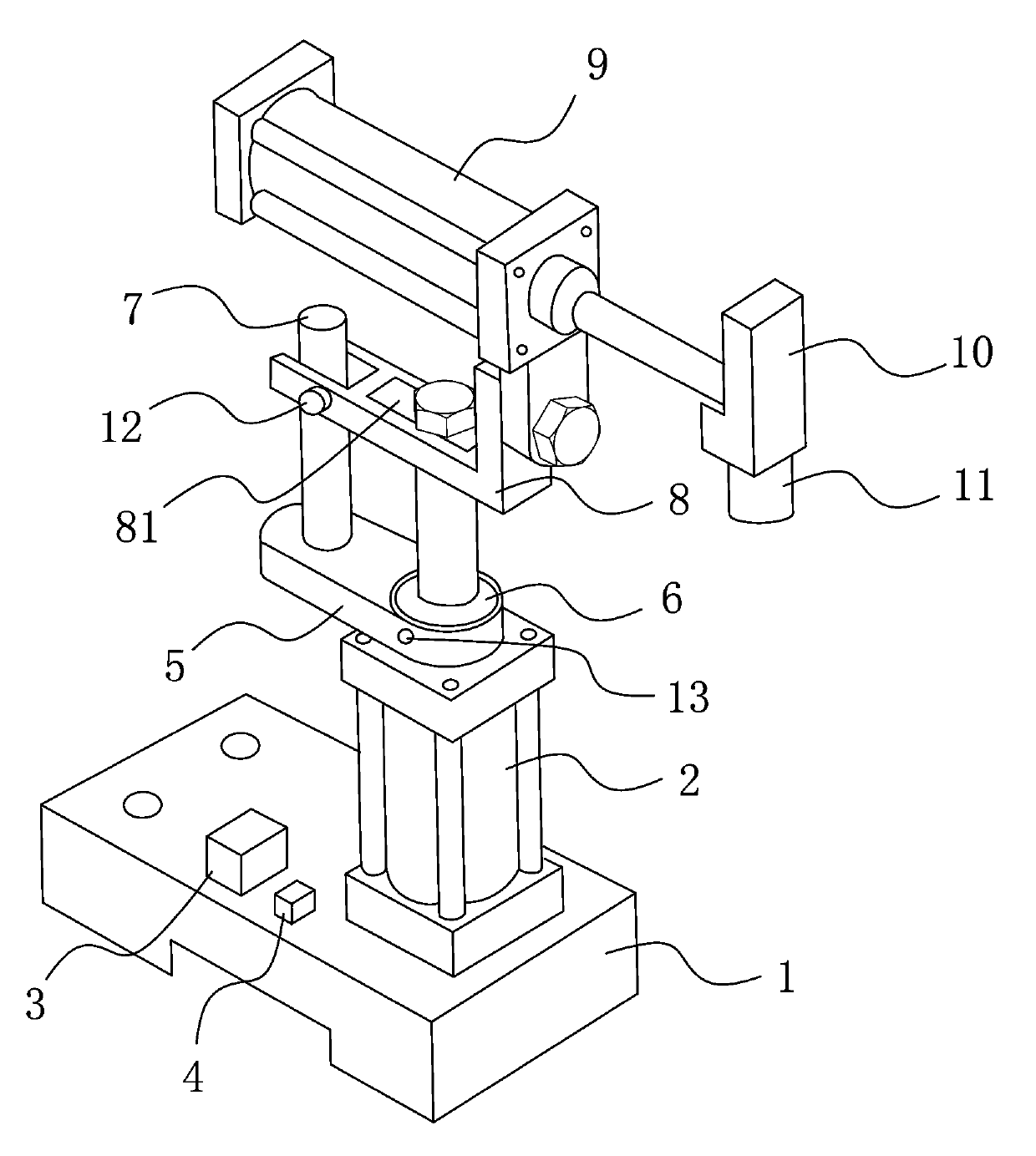
[0011] Such as figure 1 As shown, a position-adjustable magnetic adsorption manipulator includes a base 1 with mounting holes, a power structure and a grabbing structure. The power structure includes a vertical cylinder 2 and a horizontal cylinder 9, and the ends of the vertical cylinder 2 are connected to On the base 1; the grasping structure includes a mounting plate 10, an electromagnet 11 connected to the bottom of the mounting plate 10, a storage battery 3 and an electronic timer 4, the mounting plate 10 is connected to the piston rod end of the horizontal cylinder 9, and the storage battery 3 is arranged on On the base 1, the coil in the electromagnet 11 is electrically connected with the electronic timer 4 and the storage battery 3 in sequence; wherein, the connecting plate 8 is provided with a guide groove and a strip-shaped hole 81, and the piston rod of the vertical cylinder 2 passes through the The elongated hole 81 is fixedly connected with the bottom of the horizo...
PUM
 Abstract
Description
Claims
Application Information