Manipulator based on torsion spring anti-loosening structure

A torsion spring and manipulator technology, applied in the field of manipulators, can solve problems such as affecting the gripping space of the manipulator, increasing the manipulator, etc., and achieve the effects of small occupied space, simplified control system requirements, and fast real-time response.

Inactive Publication Date: 2014-03-12
SHANGHAI INST OF TECH
View PDF7 Cites 2 Cited by
  • Summary
  • Abstract
  • Description
  • Claims
  • Application Information

AI Technical Summary

Problems solved by technology

Since the anti-loosening spring is between the two fingers, it affects the grasping space of the manipulator. To grasp slightly larger objects, the structure of the manipulator must be enlarged.

Method used


Image

  • Manipulator based on torsion spring anti-loosening structure
  • Manipulator based on torsion spring anti-loosening structure
  • Manipulator based on torsion spring anti-loosening structure

Examples


Embodiment Construction

[0014] The present invention will be further described below in conjunction with the accompanying drawings and embodiments.

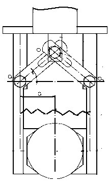
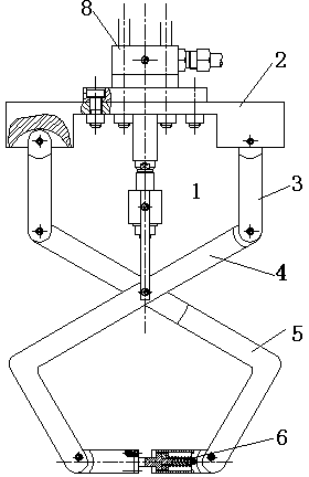
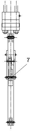
[0015] Such as figure 2 , as shown in 3, a manipulator based on a torsion spring anti-loosening structure, including a working rod 1, a fixed plate 2, a swing rod 3, a left manipulator finger 4, a right manipulator finger 5, a fingertip assembly 6, and a torsion spring anti-loosening assembly 7 , action mechanism 8.

[0016] Both sides of the lower end of the fixed plate 2 are respectively hinged to the left and right manipulator fingers 4,5 through the swing rod 3, and the middle of the left and right manipulator fingers 4,5 are hinged together, and the torsion spring anti-loosening assembly 7 is arranged at the hinge. Such as Figure 4 As shown, the two ends of the torsion spring 9 in the torsion spring anti-loosening assembly 7 are respectively fixed in the left and right manipulator fingers 4,5, and the left and right manipulator fingers 4,5 lowe...


PUM


Abstract

The invention relates to a manipulator based on a torsion spring anti-loosening structure. The two sides of the lower end of a fixed plate are respectively hinged to a left manipulator finger and a right manipulator finger through swinging rods; the middle parts of the left manipulator finger and the right manipulator finger are hinged together; a torsion spring anti-loosening component is arranged at the hinged position of the left manipulator finger and the right manipulator finger; the two ends of a torsion spring in the torsion spring anti-loosening component are respectively fixed in the left manipulator finger and the right manipulator finger; the lower ends of the left manipulator finger and the right manipulator finger are respectively hinged to compression springs and force measurement sensor components. The anti-loosening structure of the manipulator based on the torsion spring anti-loosening structure takes the torsion spring arranged between the manipulator fingers as a main anti-loosening component, and meanwhile, a pair of compression springs is arranged at the finger tip positions to serve as auxiliary loosening elements. Because of the existence of clamping force in work, the energy consumption of a power source can be reduced effectively. The structure has small occupied space and work reliability, and does not influence the space of the manipulator for grabbing an object. The grabbing force of the manipulator for grabbing the object can be controlled conveniently by matching the force measurement sensors between the fingers.

Description

technical field [0001] The invention relates to a manipulator, in particular to a manipulator that can adapt to the requirements of pressure on the surface of different grasped objects. Background technique [0002] The manipulator is also known as an automatic operation device that can imitate certain movement functions of the human hand and arm to grab, carry objects or operate tools according to a fixed program. It can replace human heavy labor to realize the mechanization and automation of production, and can operate in harmful environments to protect personal safety, so it is widely used in machinery manufacturing, metallurgy, electronics, light industry and atomic energy and other departments. When designing the manipulator, it is necessary not only to ensure a certain opening and closing size range to meet the requirements of workpiece size changes, but also to ensure that the fingers have sufficient clamping force on the workpiece and anti-loosening devices to achiev...

Claims


Application Information

Patent Timeline
Patent Type & Authority Applications(China)
IPC IPC(8): B25J9/08
Inventor 石钢黄群温有才
Owner SHANGHAI INST OF TECH
Why Eureka
Try Eureka