Crane and suspension arm thereof

A technology of cranes and booms, which is applied in the field of cranes, and can solve the problems of crane rollover, increased possibility of outrigger 19 lifting off the ground, and increased pressure

Active Publication Date: 2014-03-12
ZOOMLION HEAVY IND CO LTD
View PDF3 Cites 1 Cited by
  • Summary
  • Abstract
  • Description
  • Claims
  • Application Information

AI Technical Summary

Problems solved by technology

[0005] figure 2 In, the slewing table of the crane from figure 1 The position in the center has been rotated by 45°. At this time, the line connecting the center of the extension ends of the two legs 19 on the front side of the crane and the extension end of the two legs 19 of the crane on the side where the boom rotates to The connecting line in the center is the dangerous overturning line 20. Since the crane needs to rotate the entire boom when operating sideways, the rotary inertia of the whole machine is large, and the anti-overturning stability of the crane is relatively figure 1 The state in the middle becomes worse, and when the wind is affected, the anti-overturning stability of the crane will be further deteriorated. The boom of the crane and the hanging object form an overturning moment, and the self-weight of the crane forms a stabilizing moment. The center of gravity of the main body 15 of the crane is represented by A The position of the center of gravity of the boom is represented by B, and the position of the center of gravity of the hanging object is represented by C. When hoisting, the pressure on a leg 19 located at the front of the crane and on the side to which the boom rotates increases, and this leg 19 The outriggers 19 in a diagonal relationship increase the possibility of lifting off the ground, and the possibility of the crane rollover increases

Method used


Image

  • Crane and suspension arm thereof
  • Crane and suspension arm thereof
  • Crane and suspension arm thereof

Examples


Embodiment Construction

[0041] Specific embodiments of the present invention will be described in detail below in conjunction with the accompanying drawings. It should be understood that the specific embodiments described here are only used to illustrate and explain the present invention, and are not intended to limit the present invention.

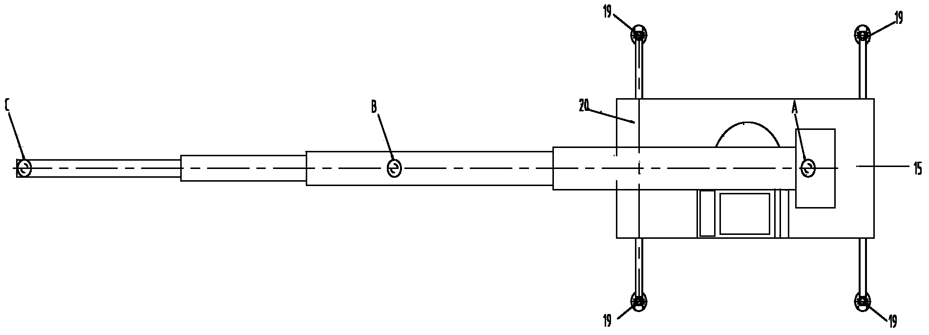
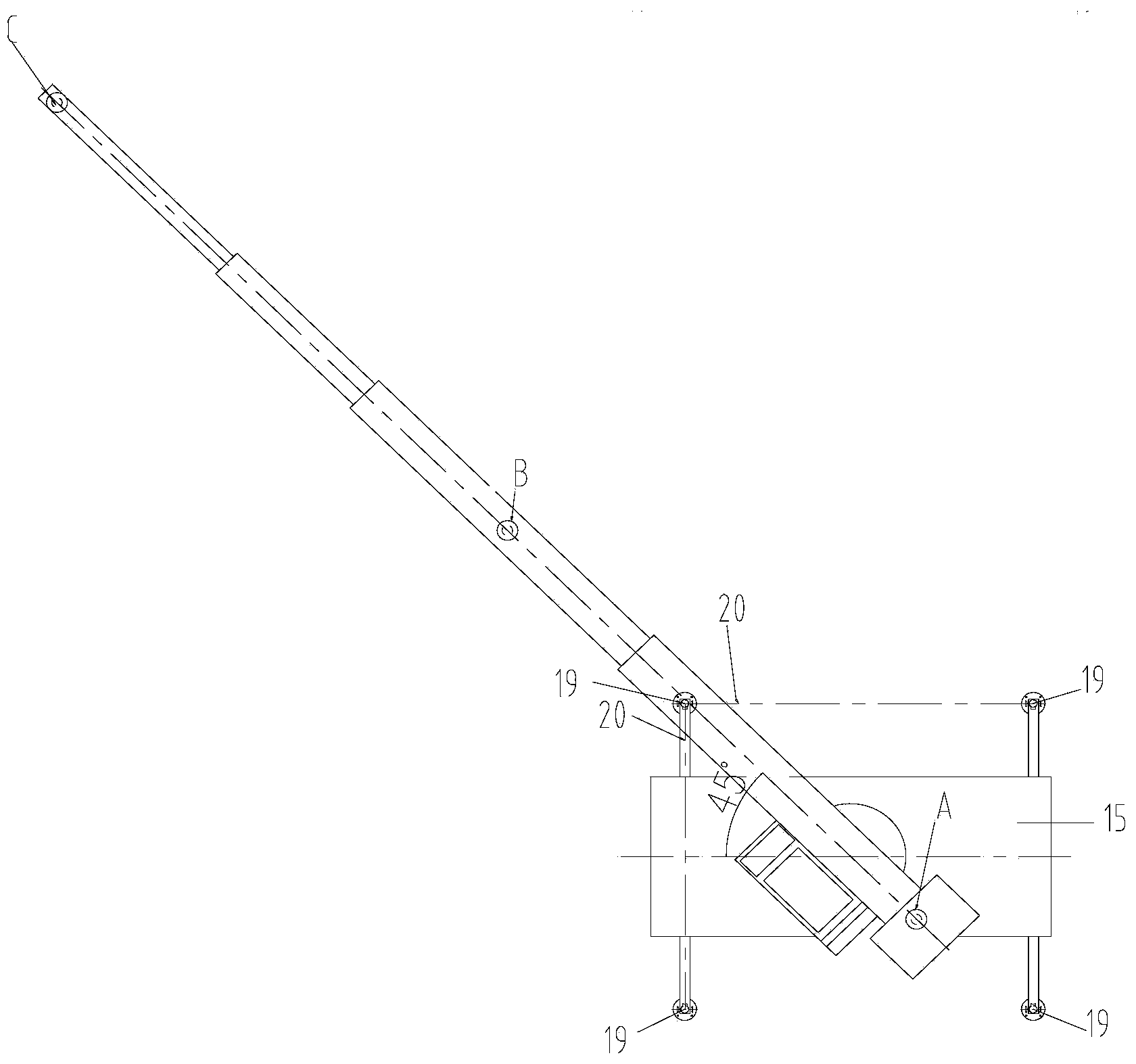
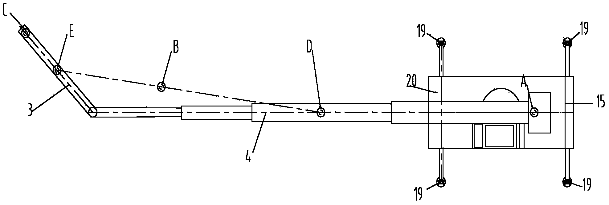
[0042] In the present invention, in the case of no contrary description, the used orientation words such as "up, down, left and right" usually refer to the up, down, left and right shown in the accompanying drawings; "inside and outside" Refers to the inside and outside of the outline of each part itself. Wherein, the "distal end" of the boom, swivel arm or base arm refers to the end of the boom, swivel arm or base arm close to the spreader respectively, and the "near end" of the boom, swivel arm or base arm refers to the boom, The end of the swivel or foundation arm that is close to the main body of the crane.

[0043] The invention provides a boom, which com...


PUM


Abstract

The invention discloses a crane and a suspension arm thereof. The suspension arm comprises a basic arm (4) and a rotating arm (3), wherein the first end of the basic arm (4) is connected to the main body (15) of the crane; the first end of rotating arm (3) can be rotationally connected with the second end of the basic arm (4); the rotating arm (3) can rotate in the rotating plane, in which the amplitude variation plane of the basic arm (4) is intersected with the rotating arm (3). In the crane disclosed by the invention, since the rotating arm is arranged additionally, that the whole revolving platform rotates is not required, to achieve lateral operation of the crane, all that is needed is to rotate the rotating arm. Therefore, the stability against overturning of the crane is improved, and the side overturning of the crane can be prevented effectively.

Description

technical field [0001] The invention relates to the field of cranes, in particular to a crane and its boom. Background technique [0002] The boom of existing cranes is generally a telescopic boom, that is, it includes a plurality of relatively telescopic boom sections. The main body 15 of the crane is provided with a turntable, and the boom is installed on the turntable and can rotate with the turntable in the rotation plane. . [0003] The crane should have a certain stability (anti-overturning stability), that is, the ability of the crane to resist overturning and maintain stability under the action of its own weight and external load. The moment algebraic sum of the load to the dangerous overturning line 20 (when the crane uses the outrigger 19 to operate, the dangerous overturning line 20 is the line connecting the center of the outrigger 19) must be greater than or at least equal to 0, that is, the stability effect is positive and the overturning effect is positive. ...

Claims


Application Information

Patent Timeline
Patent Type & Authority Applications(China)
IPC IPC(8): B66C23/64
Inventor 贺满楼
Owner ZOOMLION HEAVY IND CO LTD
Why Eureka
Try Eureka