Check patentability & draft patents in minutes with Patsnap Eureka AI!

Construction method for splay supporting frame of bridge cast-in-place concrete formwork

A technology of concrete formwork and construction method, which is applied in the direction of bridges, bridge construction, erection/assembly of bridges, etc., can solve the problems that the height of the support should not be too large, cannot be satisfied, and a large amount of economic investment, etc., to achieve the effect of reducing the project cost

Active Publication Date: 2014-03-12
THE 2ND ENG CO LTD OF CHINA RAILWAY 17 BUREAU GRP
View PDF7 Cites 5 Cited by
  • Summary
  • Abstract
  • Description
  • Claims
  • Application Information

AI Technical Summary

Problems solved by technology

[0002] At present, for the formwork support frame of cast-in-place beams in China, the full-wall support method and the steel pipe pile Bailey truss system are generally used. These two structures have different degrees of disadvantages: the full-wall support method needs to be densely covered with bowl buckle brackets or fasteners. Type steel pipe support, on which a formwork system is set; this form has lower requirements for the foundation, but the steel pipe spacing is small, the conventional spacing is between 30 and 90cm, which cannot meet the requirements for passing below, and the height of the support should not be too large, generally used for 15m height within
The steel pipe pile Bailey truss system is equipped with a formwork system on the shellfish truss, and a steel pipe with a larger diameter is installed below it as the stress system. High requirements for temporary foundations, and a large amount of economic investment is required temporarily

Method used


Image

  • Construction method for splay supporting frame of bridge cast-in-place concrete formwork
  • Construction method for splay supporting frame of bridge cast-in-place concrete formwork
  • Construction method for splay supporting frame of bridge cast-in-place concrete formwork

Examples


Embodiment Construction

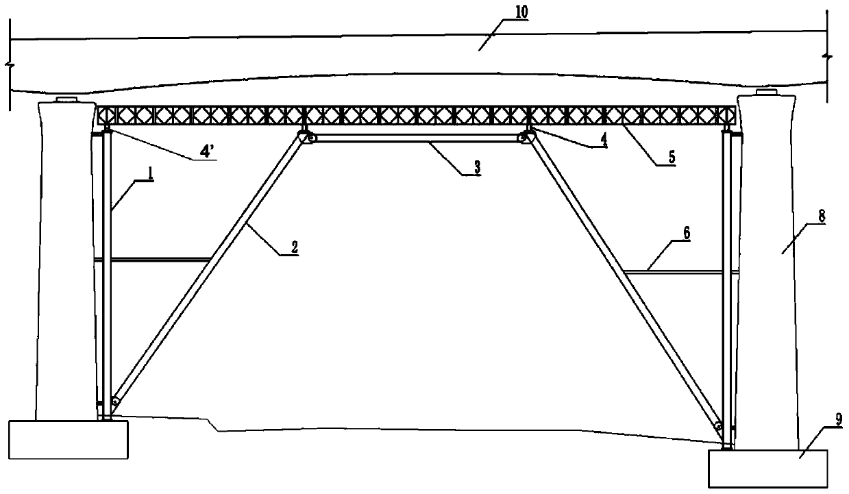
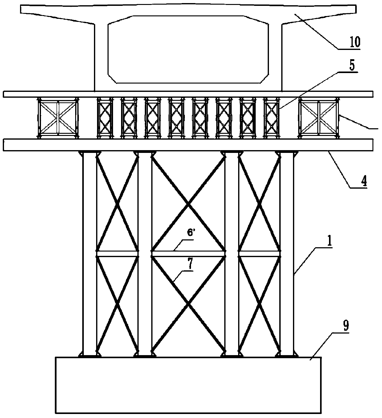
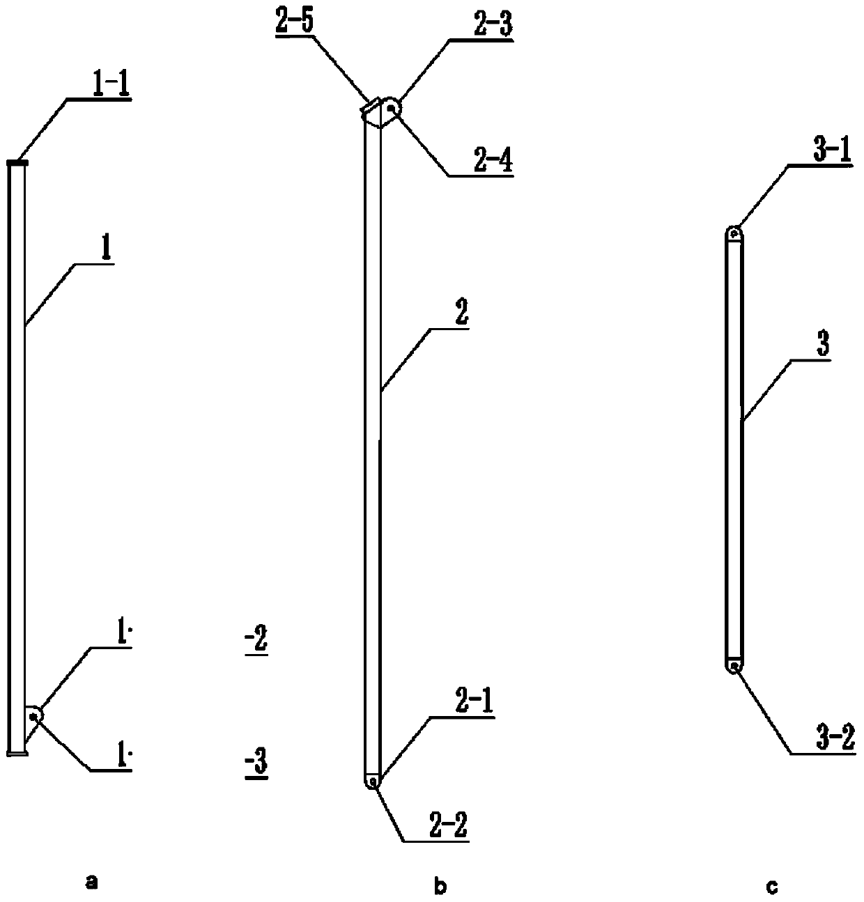
[0020] Such as figure 1 , figure 2 As shown, a bridge cast-in-place concrete formwork splayed support frame includes vertical bars 1, inclined legs 2, top braces 3, distribution beams 4, Bailey trusses 5, etc., wherein the vertical bars 1 are made of steel pipes, flanges 1-1 and gusset plate 1-2 ( image 3 a), the gusset plate 1-2 is provided with pin holes 1-3; the oblique leg 2 is composed of steel pipes, gusset plates 2-1, 2-3, pin holes 2-2, 2-4, and bearing support 2-5 ( image 3 b); the top support 3 is composed of steel pipes, gusset plates 3-1, and pin holes 3-2 ( image 3 c). The pin hole 1-3 on the gusset plate 1-2 of the vertical bar 1 is connected with the pin hole 2-2 on the gusset plate 2-1 of the diagonal leg 2 through a steel pin; the pin hole 2-2 on the gusset plate 2-3 of the diagonal leg 2 4 is connected with the pin hole 3-2 on the gusset plate 3-1 of the top support 3 by a steel pin.

[0021] Such as image 3 As shown, the vertical bar 1 is a seamle...


PUM


Abstract

The invention discloses a construction method for a splay supporting frame of a bridge cast-in-place concrete formwork. Multiple vertical rods are lined up in the transverse direction of a bridge on the inner sides of two pier studs in the longitudinal direction of the bridge. The lower ends of all the vertical rods and pier stud pile caps are anchored, and the lower portions, the middle portions and the upper portions of all the vertical rods are anchored to pier stud bodies respectively. The upper ends of the vertical rods are connected through end distribution beams. In the transverse direction of the bridge, the middle portions of all the vertical rods are mutually connected through cross arms in the transverse direction. The lower ends of all the vertical rods are respectively connected with the lower ends of inclined legs, and the upper ends of the two inclined legs in the longitudinal direction of the bridge are connected through a back shore. The middle portions of the inclined legs in the longitudinal direction of the bridge are connected with the middle portions of the vertical rods through cross arms in the longitudinal direction. The middle portions of all the inclined legs in the transverse direction of the bridge are connected through cross arms in the transverse direction. The upper ends of all the inclined legs are connected through middle distribution beams. Multiple bailey trusses manufactured in advance are installed on the end distribution beams and the middle distribution beams in the longitudinal direction of the bridge, so that the splay support stable structure is formed. According to the construction technology, underneath passage can not be affected, no temporary foundation is needed, installation and detaching are easy, and the cyclic utilization rate is high.

Description

technical field [0001] The invention relates to the construction technology of cast-in-place concrete for bridges, in particular to a construction method for a cast-in-place beam formwork support frame. Background technique [0002] At present, for the formwork support frame of cast-in-place beams in China, the full-wall support method and the steel pipe pile Bailey truss system are generally used. These two structures have different degrees of disadvantages: the full-wall support method needs to be densely covered with bowl buckle brackets or fasteners. Type steel pipe support, on which a formwork system is set; this form has lower requirements for the foundation, but the steel pipe spacing is small, the conventional spacing is between 30 and 90cm, which cannot meet the requirements for passing below, and the height of the support should not be too large, generally used for 15m height within. The steel pipe pile Bailey truss system is equipped with a formwork system on the...

Claims


Application Information

Patent Timeline
IPC IPC(8): E01D21/00
Inventor 陈进明
Owner THE 2ND ENG CO LTD OF CHINA RAILWAY 17 BUREAU GRP
Features
  • R&D
  • Intellectual Property
  • Life Sciences
  • Materials
  • Tech Scout
  • Unparalleled Data Quality
  • Higher Quality Content
  • 60% Fewer Hallucinations
Learn More