Top support type automatic grouting valve type float valve

An automatic grouting and top-supporting technology, which is applied in the direction of wellbore/well components, earthwork drilling, flushing wellbore, etc., can solve the problems of automatic grouting, etc., and achieve the goal of avoiding blowout in the pipe, reducing pressure excitement, and reducing labor intensity Effect

Inactive Publication Date: 2014-03-12
慕武
View PDF6 Cites 1 Cited by
  • Summary
  • Abstract
  • Description
  • Claims
  • Application Information

AI Technical Summary

Problems solved by technology

Avoid the disadvantages of the current valve type float valve that cannot be automatically grouted

Method used


Image

  • Top support type automatic grouting valve type float valve
  • Top support type automatic grouting valve type float valve

Examples


Embodiment Construction

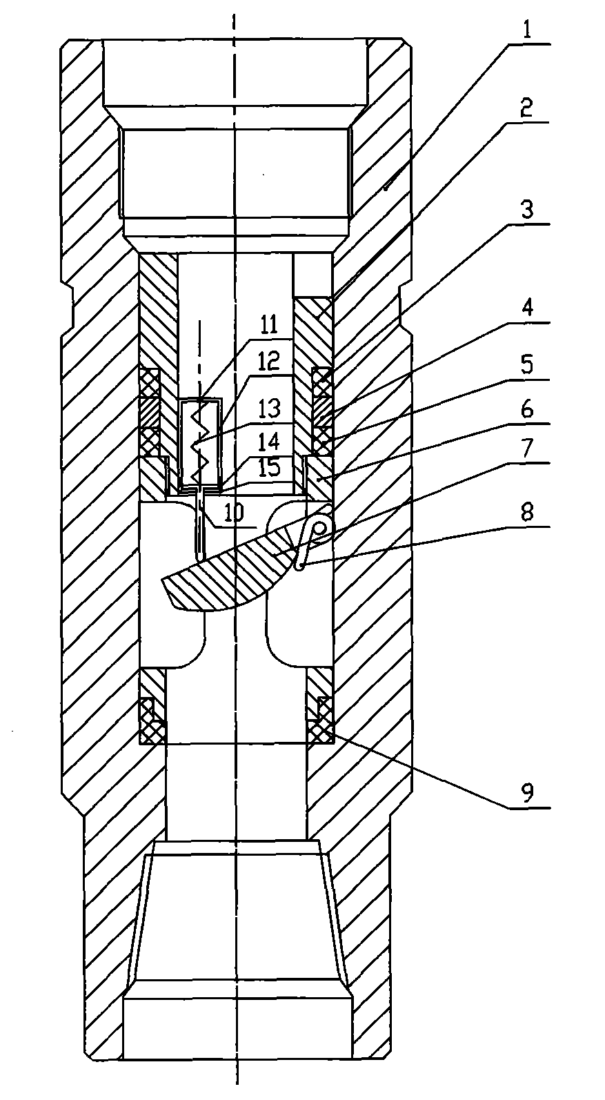
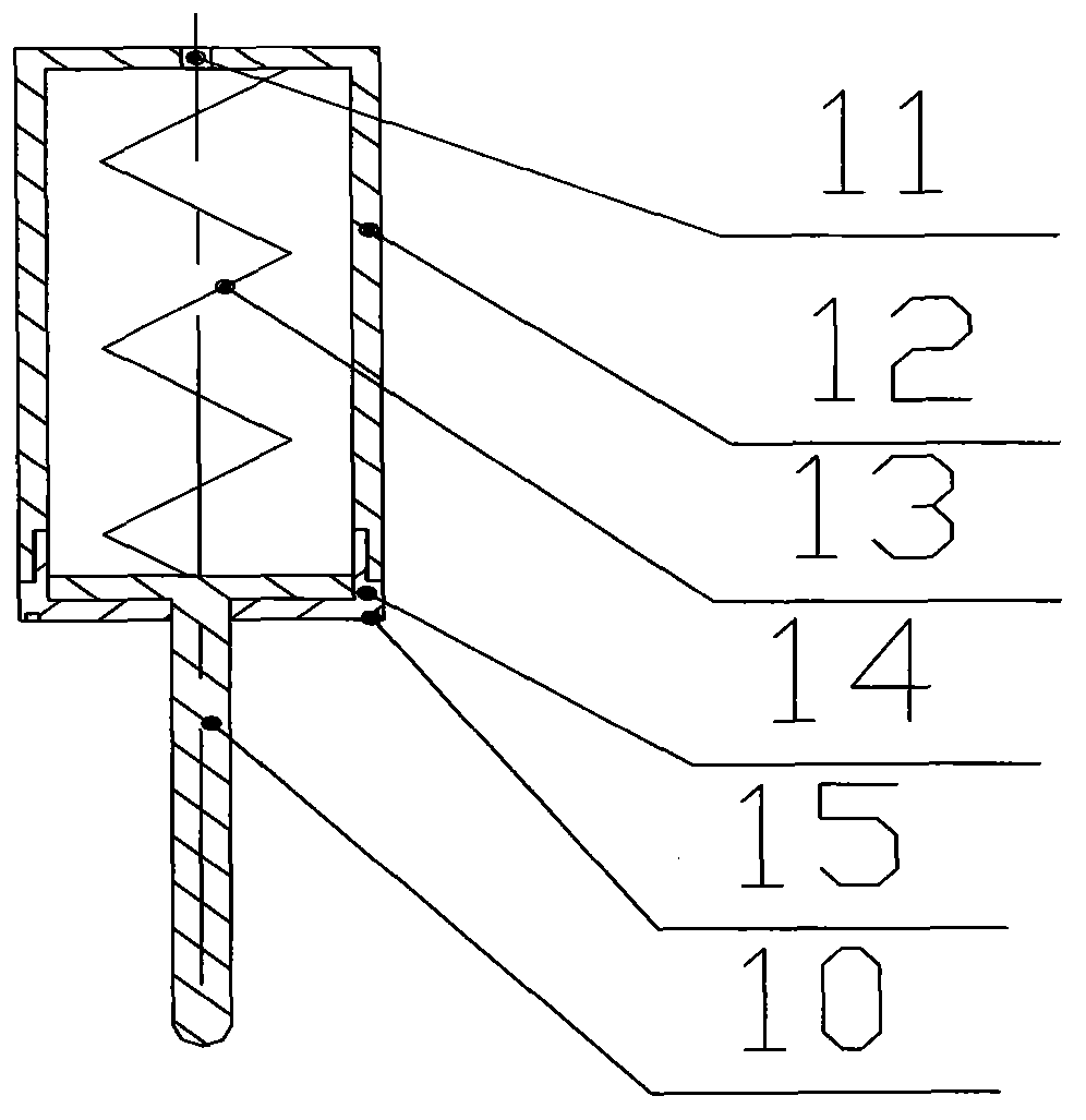
[0012] Such as figure 1 As shown, a top-supported automatic grouting valve float valve includes a float valve joint 1, a float valve and a valve top support device. Float valve is made of upper valve body 2, upper sealing ring 3, gasket ring 4, middle sealing ring 5, valve body seat 6, valve 7, torsion spring 8, lower sealing ring 9. The upper valve body 2 is connected with the valve body seat 6 with threads, the upper sealing ring 3, the gasket ring 4 and the middle sealing ring 5 are set on the upper valve body 2, and the inner diameter of the float valve is basically the same as that of the float valve joint 1 There is an inner convex shoulder surface on the inner wall of the float valve joint 1, the float valve is placed in the float valve joint 1, and the lower end of the lower sealing ring 9 sleeved on the lower end of the valve body seat 6 pushes against the inner convex shoulder surface to form a seal. When the valve joint 1 is connected with the drilling tool, the sm...


PUM


Abstract

The invention discloses a top support type automatic grouting valve type float valve. The top support type automatic grouting valve type float valve is characterized in that a float valve body is mounted inside a float valve connector, and a valve top support device is welded inside the float valve body. A valve is hinged to a valve type valve body seat of the float valve body. Elastic force of a torsional spring on the valve type valve body seat enables the valve type valve body seat to be closed by the valve when the valve is in a free state. The closing spring force for automatic closing of the valve of the valve type float valve and the force for flowing towards the inside of a tube due to the inside and outside differential pressure of fluid inside a well can be balanced by the top support device according to the principle that a top support spring has certain support force (the spring force can be adjusted by the way of changing the size of the spring). A top support rod enables the valve to be in a slightly open state all the time, a channel is formed, and the purpose of automatic grouting is achieved. When well kick or blowout happens to the inside of the tube, the valve is under the action of the fluid flowing towards the inside the tube, the top support spring is compressed by the top support rod, the top support rod retracts the inside of a top support box, the valve is closed, the purpose of a check valve is achieved, the well kick and blowout accident inside the tube is prevented, and the defect that automatic grouting can not be achieved by an existing valve type float valve is overcome.

Description

technical field [0001] The invention relates to the method of manual grouting without stopping the drilling (oil pipe running) operation in the oil drilling process, which can be automatically grouted. When the flow velocity of fluid in the pipe such as well kick and blowout reaches a certain value, it will play the role of a check valve, which can prevent the occurrence of blowout accidents in the pipe when pulling out the drill. Background technique [0002] In the process of drilling (tubing) in oil drilling, because the valve type float valve commonly used in the field only plays the role of a check valve, and because of the limitation of the pressure bearing capacity and the compression strength of the drill pipe (tubing), the running (running) When the oil pipe) reaches a certain well depth, in order to prevent the valve type float valve from being invalid due to the excessive pressure, it is easy to cause well kick or even blowout accident in the pipe, prevent the dri...

Claims


Application Information

Patent Timeline
Patent Type & Authority Applications(China)
IPC IPC(8): E21B21/10
Inventor 慕武慕渊明杨健彬陈元袁伟陈永衡刘金荣赵瑞明张猛张廷武
Owner 慕武
Why Eureka
Try Eureka