Solar hot water temperature gradient manifold

A solar hot water and temperature gradient technology, applied in the field of connecting pipelines, can solve the problems that the hot water is difficult to quickly meet the use requirements, the connecting pipes cannot be disassembled, and the connecting pipes are a lot of dirt, so as to reduce the growth of bacteria, the structure is simple, and the water quality is guaranteed. Effect

Inactive Publication Date: 2014-03-12
GUANGXI JIKUAN SOLAR ENERGY EQUIP
View PDF0 Cites 0 Cited by
  • Summary
  • Abstract
  • Description
  • Claims
  • Application Information

AI Technical Summary

Problems solved by technology

It uses vacuum heat collecting tubes to absorb solar energy, and then conducts heat exchange with the water storage tank, and finally achieves the purpose of heating water, but due to the limitation of solar energy collection efficiency, it is difficult for the hot water in the water storage tank to quickly meet the use requirements, resulting in a kind of Hot water system with multi-stage (heated) tanks
However, the connecting pipes between existing solar multi-stage water tanks are simply connected, because the temperature between different water tanks is the same, so the simple connection of multi-stage (heating) is no different from the overall water tank, and it is difficult to make hot water flow quickly to the hot water tank. Water requires a water outlet for use. Normally, the connecting pipe cannot be disassembled. After long-term use, there will be a lot of dirt in the connecting pipe, making it difficult to clean

Method used


Image

  • Solar hot water temperature gradient manifold
  • Solar hot water temperature gradient manifold
  • Solar hot water temperature gradient manifold

Examples


Embodiment Construction

[0024] In order to make the technical means, creative features, goals and effects achieved by the present invention easy to understand, the present invention will be further described below in conjunction with specific illustrations.

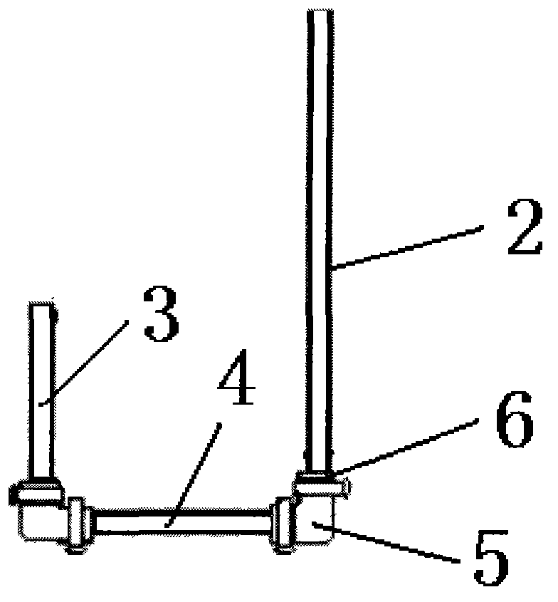
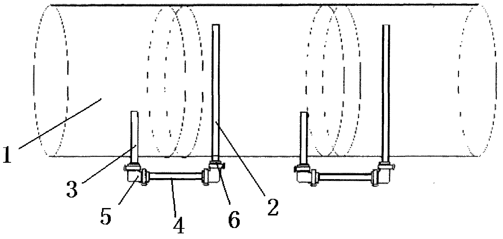
[0025] refer to Figure 1-2 As shown, a solar hot water temperature gradient shunt pipe adopts an external connection and is arranged between two solar water tanks 1 with a temperature difference, including a long pipe 2, a short pipe 3, and a connecting pipe 4. The long pipe 2 is arranged on the In the solar water tank 1 with low temperature, its end is placed on the upper part of the solar water tank 1; the short pipe 3 is arranged in the solar water tank 1 with high temperature, and its end is placed in the lower part of the solar water tank 1, and the long pipe 2 and the short pipe 3 are connected by The tubes 4 are connected to each other and form a U-shaped structure. The two ends of the connecting tube 4 are respectively connected to the ...


PUM


Abstract

The invention relates to a solar hot water temperature gradient manifold. The solar hot water temperature gradient manifold is designed according to the fluid thermodynamic temperature gradient principle. The solar hot water temperature gradient manifold is used for enabling hot water to carry out flow division according to a certain gradient temperature, and is arranged between two solar water tanks with the temperature grade difference. The solar hot water temperature gradient manifold comprises a long pipe, a short pipe and a connecting pipe, wherein the long pipe is arranged in the solar water tank with the lower water temperature, and the tail end of the long pipe is arranged on the upper portion of the solar water tank; the short pipe is arranged in the solar water tank with the higher water temperature, and the tail end of the short pipe is arranged on the lower portion of the solar water tank; the long pipe is connected with the short pipe through the connecting pipe. The solar hot water temperature gradient manifold has the advantages that hot water on the upper layer of the solar water tank with the lower water temperature can be conveyed to the solar water tank with the higher water temperature, and conveying flow of the hot water, with the higher temperature, between multi-level heating water tanks is quickened. The solar hot water temperature gradient manifold is simple in structure, snap rings and silica gel elbows can be freely disassembled, and cleaning is convenient; due to the fact that anti-bacterial layers are arranged on the inner wall of the long pipe, the inner wall of the short pipe and the inner wall of the connecting pipe respectively, bacteria breeding is reduced, and water quality is ensured.

Description

technical field [0001] The invention relates to the technical field of connecting pipelines, in particular to a solar hot water temperature gradient shunt pipe. Background technique [0002] Solar water heaters have been widely promoted and applied. Existing solar water heaters mainly consist of vacuum heat collecting tubes, heat preservation water storage tanks and supports. The water storage tank is a single water tank structure. Lead out from the upper part of the water storage tank. It uses vacuum heat collecting tubes to absorb solar energy, and then conducts heat exchange with the water storage tank, and finally achieves the purpose of heating water, but due to the limitation of solar energy collection efficiency, it is difficult for the hot water in the water storage tank to quickly meet the use requirements, resulting in a kind of Hot water system with multi-stage (heating) tanks. However, the connecting pipes between existing solar multi-stage water tanks are simp...

Claims


Application Information

Patent Timeline
Patent Type & Authority Applications(China)
IPC IPC(8): F24J2/46
CPCY02E10/40
Inventor 马昭键蒙献芳陆俊行潘以义林成刚周凡谢刚杨明慧
Owner GUANGXI JIKUAN SOLAR ENERGY EQUIP
Why Eureka
Try Eureka