Pulsating heat pipe with roughening structure

A pulsating heat pipe and roughening technology, applied in indirect heat exchangers, lighting and heating equipment, etc., can solve the problems of long start-up time, limit the application of pulsating heat pipes, and start-up temperature rise, and achieve broad application prospects and shorten the start-up time. Effect

Inactive Publication Date: 2014-03-12
SOUTH CHINA UNIV OF TECH
View PDF8 Cites 10 Cited by
  • Summary
  • Abstract
  • Description
  • Claims
  • Application Information

AI Technical Summary

Problems solved by technology

The traditional pulsating heat pipe is made of capillary bends, the wall surface is relatively smooth, and the heat flux needs to reach a certain level before it can be started, resulting in a too high start-up temperature rise beyond the allowable temperature range of the equipment, thereby affecting the performance of the equipment, and at the same time, it takes a long time start-up time, which limits the practical application of pulsating heat pipes

Method used


Image

  • Pulsating heat pipe with roughening structure

Examples


Embodiment

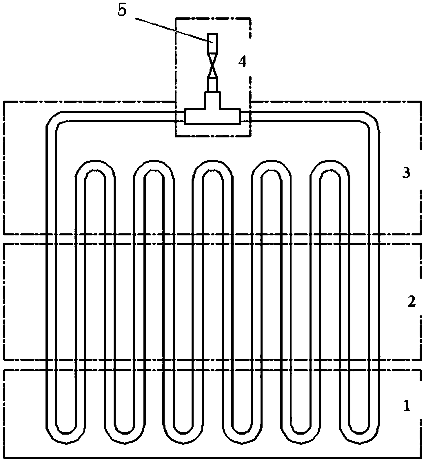
[0013] Such as figure 1 shown. The present invention has a pulsating heat pipe with a coarser structure, and acetone is poured into the pulsating heat pipe as a working medium; the pulsating heat pipe includes an evaporation section 1, a heat insulation section 2, a condensation section 3 and a working fluid perfusion section 4; the heat insulation section 2 and The condensation section 3 is integrally formed by capillary tubes; the connection between the evaporation section 1 and the heat insulation section 2 is welding; the two interfaces of the working fluid injection section 4 communicate with the tee pipe 5; the inner wall of the evaporation section 1 The surface is a granular structure (roughened structure), which can be processed by electroplating, electrochemical corrosion, chemical corrosion or powder sintering. The roughened structure helps to increase the radius of the nucleation point, which in turn facilitates the formation of new bubbles on the inner wall of the...


PUM


Abstract

The invention discloses a pulsating heat pipe with a roughening structure. Acetone is injected into the pulsating heat pipe to serve as a work medium. The pulsating heat pipe comprises an evaporation section, a heat insulation section, a condensation section and a work medium injected section, wherein the heat insulation section and the condensation section are integrated through a capillary tube, the evaporation section is welded to the heat insulation section, two connecting ports of the work medium injected section are communicated with a three-way pipe, and the surface of the inner wall of the evaporation section is of a particle structure. As the surface of the inner wall of the evaporation section is of the particle structure, the lowest temperature needed by starting of the pulsating heat pipe is lowered, the pulsating heat pipe can still smoothly start and operate even under a low heat flux density condition, the starting time can be effectively shortened, and the pulsating heat pipe with the roughening structure has broad application prospects in the field of heat dissipation of electronic elements.

Description

technical field [0001] The invention relates to a cooling and heat dissipation device for electronic components, in particular to a pulsating heat pipe with a roughened structure. Background technique [0002] With the continuous improvement of the integration of electronic components, the volume of electronic equipment is getting smaller and smaller, and the functions and complexity of electronic equipment are increasing. The heat dissipation problem of the high heat flux density of the heating chip has become one of the biggest bottlenecks in the development of the microelectronics industry. The pulsating heat pipe has a good development prospect in the efficient cooling of electronic devices due to its simple and changeable structure, strong adaptability, no need for capillary core, simple manufacture, and good heat transfer performance. The pulsating heat pipe is a closed capillary circuit with serpentine bend and vacuum. After filling part of the working fluid, under t...

Claims


Application Information

Patent Timeline
Patent Type & Authority Applications(China)
IPC IPC(8): F28D15/02
Inventor 汤勇周波方朝斌袁伟张华杰李耀超
Owner SOUTH CHINA UNIV OF TECH
Why Eureka
Try Eureka