
A system and method for realizing centralized and non-disturbance conversion of equipment control mode

A device control, non-disturbance technology, applied in the field of electrical automation, can solve problems such as inability to select and convert, lack of design, increased automation engineering costs, etc., to improve centralized management and control capabilities, avoid equipment restarts, and improve the effect of equipment operation.

Active Publication Date: 2016-01-20
NORTHEASTERN UNIV LIAONING
View PDF4 Cites 0 Cited by
  • Summary
  • Abstract
  • Description
  • Claims
  • Application Information

AI Technical Summary

Problems solved by technology

[0005] Although the above equipment control mode conversion system is simple and easy to implement, it has the following deficiencies during the implementation of the distributed control automation project and the actual use of users: 1) Because the conversion switches are all set on the control box next to the machine, so The selection and conversion of equipment control methods cannot be performed in the control room, which greatly weakens the ability of the control room to control the controlled equipment on site
2) For the controlled equipment in the running state, when the transfer switch is turned from the "side control mode" gear to the "centralized control mode" gear, it will definitely cause a shutdown, which will bring some troubles
3) The transfer switches are distributed to the control boxes next to each controlled device on site, which is very inconvenient in operation to realize the simultaneous control mode conversion of multiple controlled devices
This shows a lack of design for closely interlocked equipment chains such as belt transmission systems
4) In the distributed control, it is not necessary to set up a transfer switch for each controlled device, which will cause too many points of DI digital input (digital input, the same below) on the PLC / DCS system configuration, and automation engineering Cost increase

Method used


Image

  • A system and method for realizing centralized and non-disturbance conversion of equipment control mode
  • A system and method for realizing centralized and non-disturbance conversion of equipment control mode
  • A system and method for realizing centralized and non-disturbance conversion of equipment control mode

Examples


Embodiment Construction

[0039] The present invention will be described in detail below in conjunction with the accompanying drawings and embodiments. This embodiment takes a large domestic concentrator distributed control system automation engineering project as an example to implement the technical solution of the present invention.

[0040] The concentrator has an annual output of 4 million tons of iron ore concentrate and has 4 production workshops. After the automatic distributed control system is built, the entire production process is monitored and managed by the monitoring computer in the central control room.

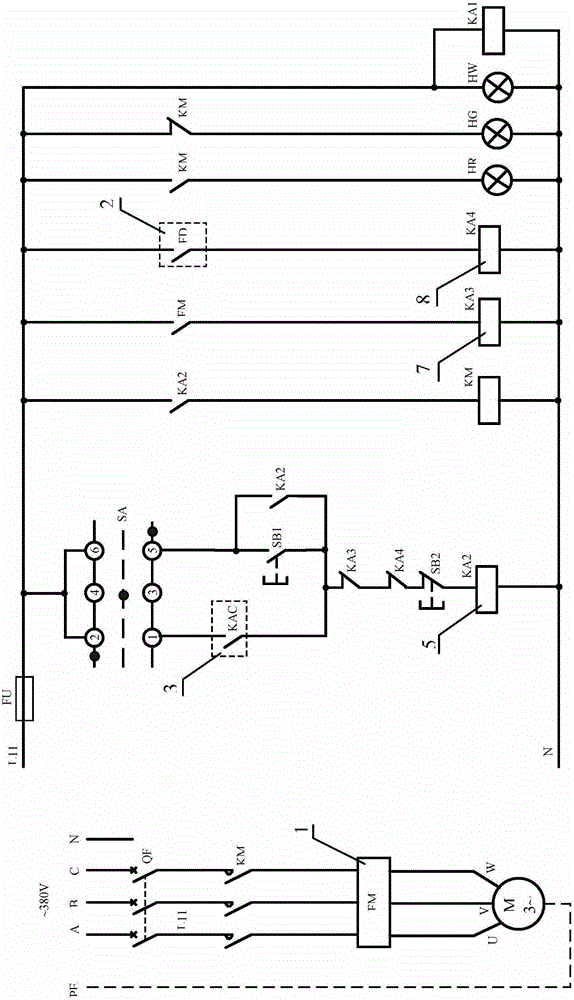
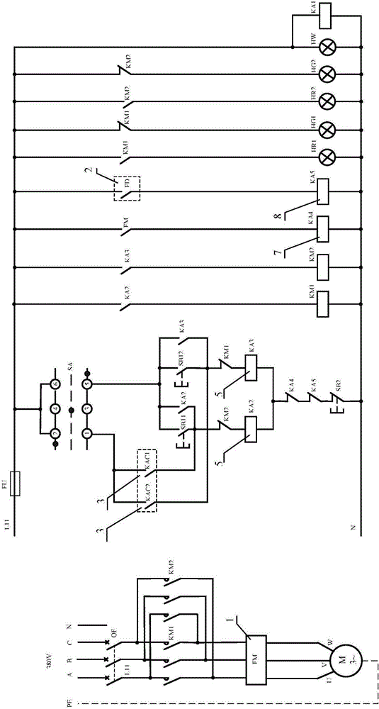
[0041] The automatic distributed control system adopts the PLC system, which controls 535 process equipments and belongs to 20 PLC control stations (including local stations or remote stations). If according to the traditional equipment control electrical control principle (such as figure 1 , figure 2 ) to design, need to use 535 changeover switches, install them on 535 control boxe...


PUM


Abstract

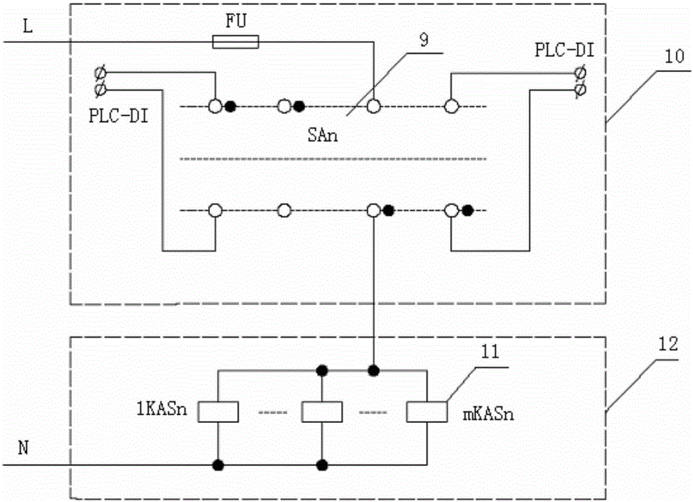
A system and method for realizing centralized non-disturbance conversion of equipment control mode. The system includes a centralized conversion electrical operating console, a centralized conversion relay and a non-disturbing conversion electrical control circuit. The centralized conversion electrical operating console is equipped with a centralized equipment control mode centralized conversion switch and a preset switch. Conversion button, each conversion switch has a "machine control mode" gear, a "centralized control mode" gear and an intermediate gear; each transfer switch controls one or more centralized transfer relays; the normally open contact of the centralized transfer relay They are respectively connected to the non-disturbance conversion electrical control loop corresponding to the transfer switch; the non-disturbance conversion electrical control loop includes the normally open contact of the equipment control relay and the equipment control intermediate relay controlled by PLC / DCS. The invention improves the control room's centralized management and control capabilities for industrial on-site process equipment, realizes disturbance-free conversion of the equipment control mode between "machineside control mode" and "centralized control mode", and facilitates normal operation or maintenance and debugging of the controlled equipment.

Description

technical field [0001] The invention belongs to the technical field of electrical automation, and in particular relates to a system and method for realizing centralized and disturbance-free switching of equipment control modes. Background technique [0002] In the distributed control of the process industry, the basic control content mainly includes equipment control and loop control. Equipment control is to control the start and stop of all process equipment in the production process according to the process and production requirements, monitor their operating status, issue alarms, and automatically shut down, etc. Generally, the drag motor of the control equipment runs in one direction (accounting for the vast majority) or runs in forward and reverse directions. There are generally two types of start-stop control methods for equipment. In normal production, the start and stop of the controlled equipment generally require commands to be issued on the monitoring computer i...

Claims


Application Information

Patent Timeline
Patent Type & Authority Patents(China)
IPC IPC(8): G05B19/048
Inventor 张杰卿吴永建丁进良李健理明明郑秀萍柴天佑
Owner NORTHEASTERN UNIV LIAONING
Learn More