Temperature difference power generation mouse

A thermoelectric power generation and mouse technology, which is applied in generators/motors, electrical components, data processing power supplies, etc., can solve problems such as insufficient power for the operation of the thermoelectric power generation mouse 10, and poor air cooling efficiency of the main casing 11, etc. To achieve the effect of effective power supply

A thermoelectric power generation and mouse technology, which is applied in generators/motors, electrical components, data processing power supplies, etc., can solve problems such as insufficient power for the operation of the thermoelectric power generation mouse 10, and poor air cooling efficiency of the main casing 11, etc. To achieve the effect of effective power supply

CN103631392AInactive Publication Date: 2014-03-12PRIMAX ELECTRONICS LTD

Image

  • Temperature difference power generation mouse
  • Temperature difference power generation mouse
  • Temperature difference power generation mouse

Examples


Embodiment Construction

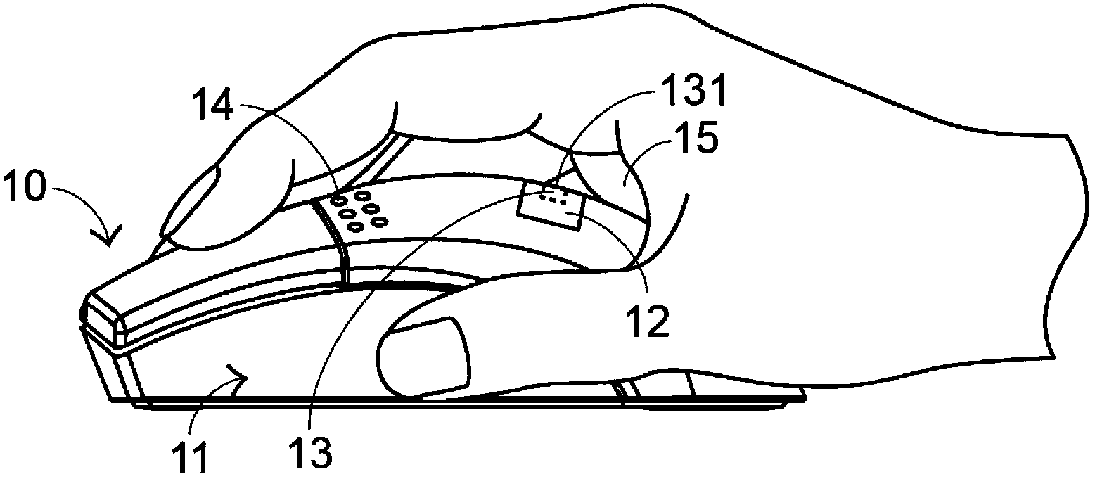
[0033] In order to improve the lack of the existing thermoelectric power generation mouse, the present invention arranges the heat conduction sheet and the thermoelectric power generation chip at the position equivalent to the button sheet, unlike the prior art where the heat conduction sheet and the thermoelectric power generation chip are arranged behind the mouse main casing end and provide cooling holes.

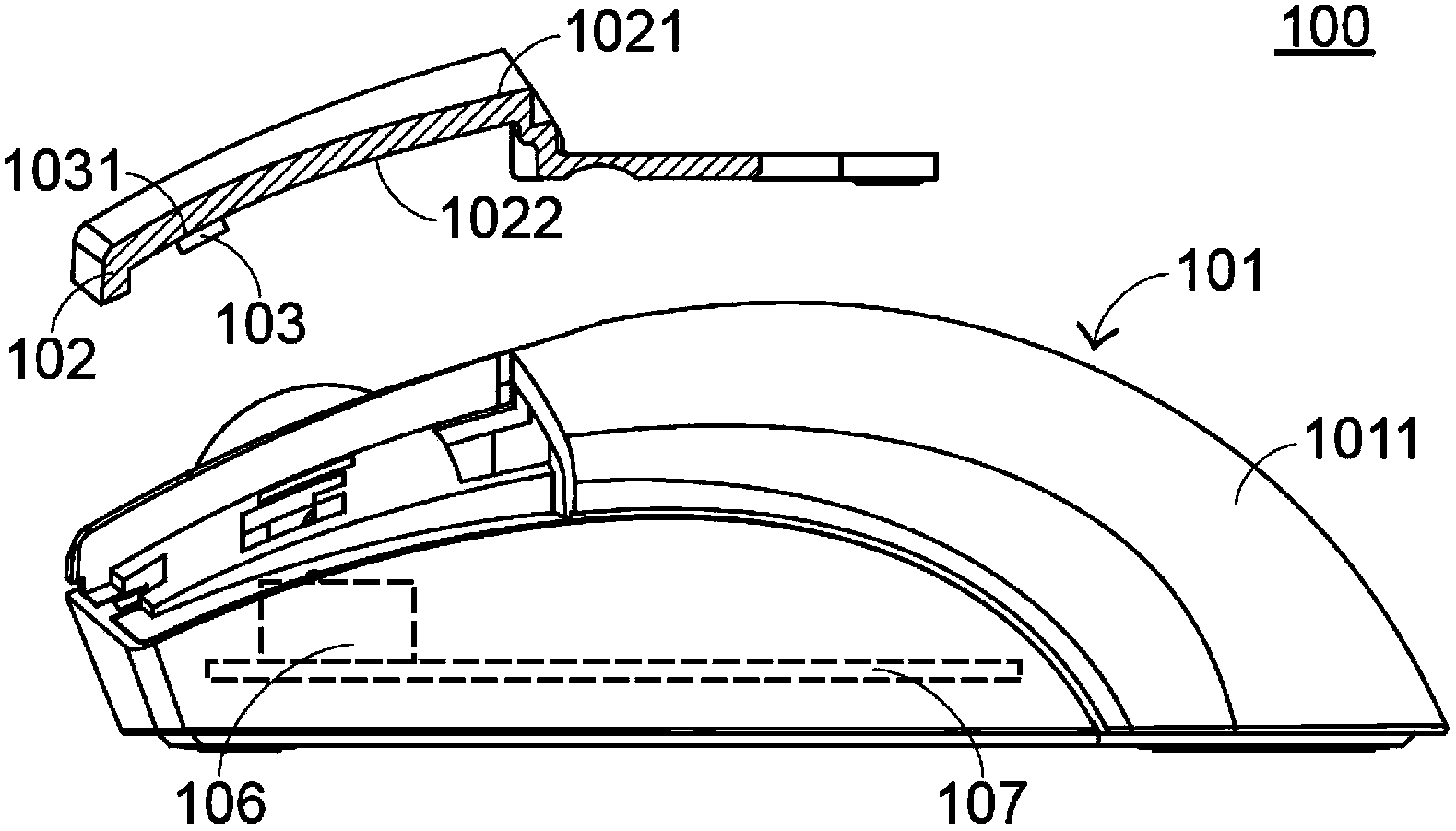
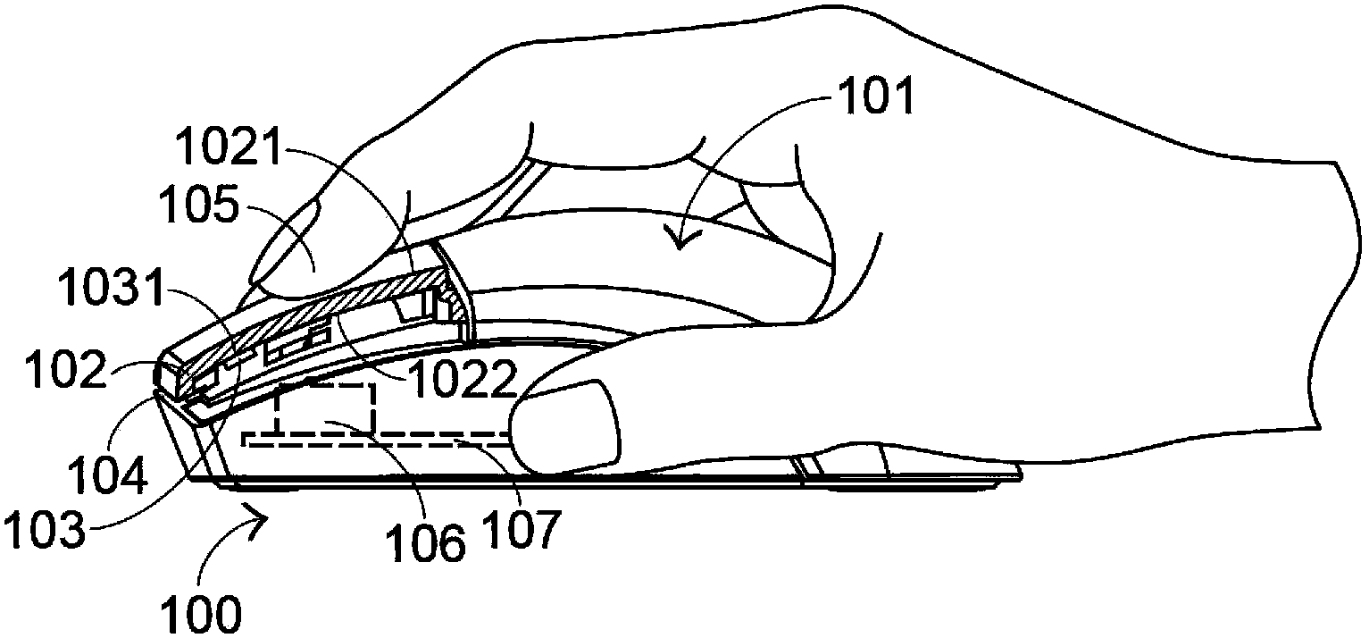
[0034] see figure 2 , which is an exploded and cross-sectional schematic diagram of the main parts of the first preferred embodiment of the thermoelectric power generation mouse of the present invention. figure 2 Among them, the thermoelectric mouse 100 includes a main casing 101 and a heat conduction sheet 102, and a first surface 1021 of the heat conduction sheet 102 extends from a surface 1011 of the main casing 101, so that the heat conduction sheet 102 and the main casing 101 jointly form a The overall appearance of the thermoelectric mouse 100. A thermoelectric...


PUM


Abstract

The invention relates to a temperature difference power generation mouse. The temperature difference power generation mouse comprises a main shell, a switch, a button piece, a heat conduction piece and a temperature difference power generation chip. The heat conduction piece penetrates through the button piece and makes contact with the temperature difference power generation chip on the lower surface of the button piece so as to guarantee the effect that the hand of a user can often touch the heat conduction piece to provide the temperature difference needed by the temperature difference power generation chip. In addition, the temperature difference power generation chip can dissipate heat through gaps at the edges of the button piece, and therefore the maximum temperature difference power generation efficiency is achieved.

Description

technical field [0001] The present invention relates to a mouse device, in particular to a mouse device powered by a thermoelectric power generation chip. Background technique [0002] The era of science and technology and information has arrived. Computers and their peripheral devices have become part of everyone's daily life. The mouse is a bridge between computers and users, and its importance is self-evident. Therefore, various Major computer-related businesses attach great importance to the mouse, and have also developed various new functions or more convenient-to-use mice. [0003] A conventional thermoelectric power generation mouse is proposed on the market, which utilizes thermoelectric power generation to provide power to the mouse. see figure 1 , which is a schematic diagram of the overall appearance and usage state of the existing thermoelectric power generation mouse. figure 1 Among them, the existing thermoelectric power generation mouse 10 has a main housin...

Claims


Application Information

Patent Timeline
12 Mar 2014
Publication
CN103631392A
IPC
G06F3/033; H02N11/00
CPC
G06F3/03543; G06F1/26; H02N11/00
Inventors
ε΄ε»Ίζ–Œ