

High-efficiency low-cost power supply for radio frequency systems
- Summary
- Abstract
- Description
- Claims
- Application Information
AI Technical Summary
Benefits of technology
Problems solved by technology
Method used
Image

Examples
first embodiment
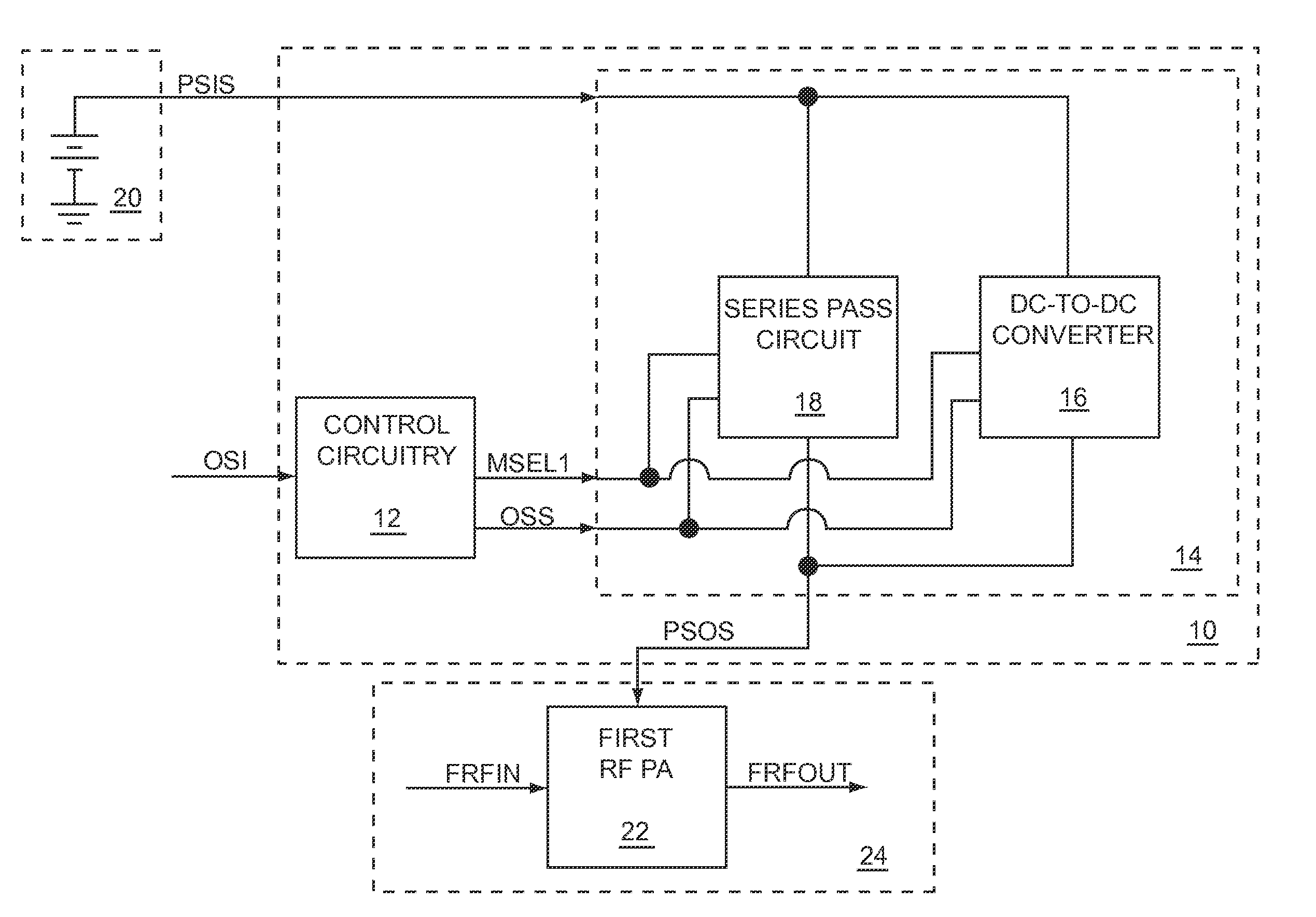
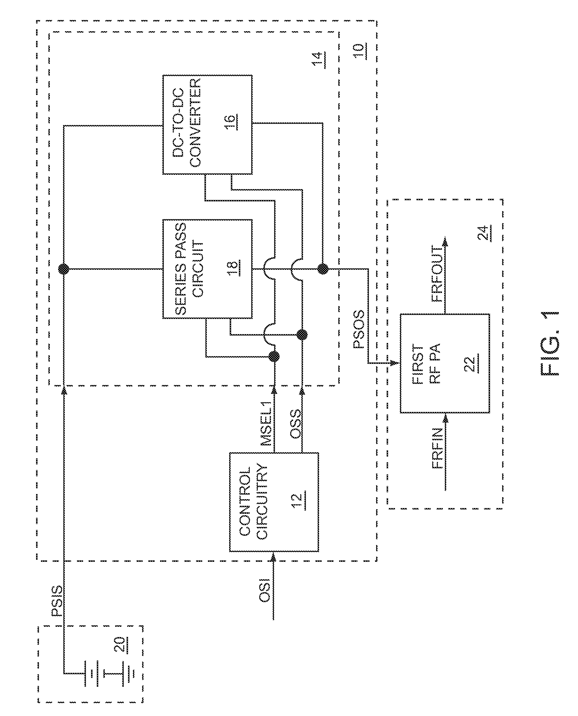
[0043]In the DC-to-DC converter 16, at least the first inductive element L1(not shown) is coupled to the switching circuitry 46, such that the first inductive element is used as an energy transfer element to provide the switching circuitry output signal SCOS during the switching supply operating mode. Specifically, the first inductive element L1 may receive energy using the power supply input signal PSIS and transfer energy to the switching circuitry output signal SCOS.
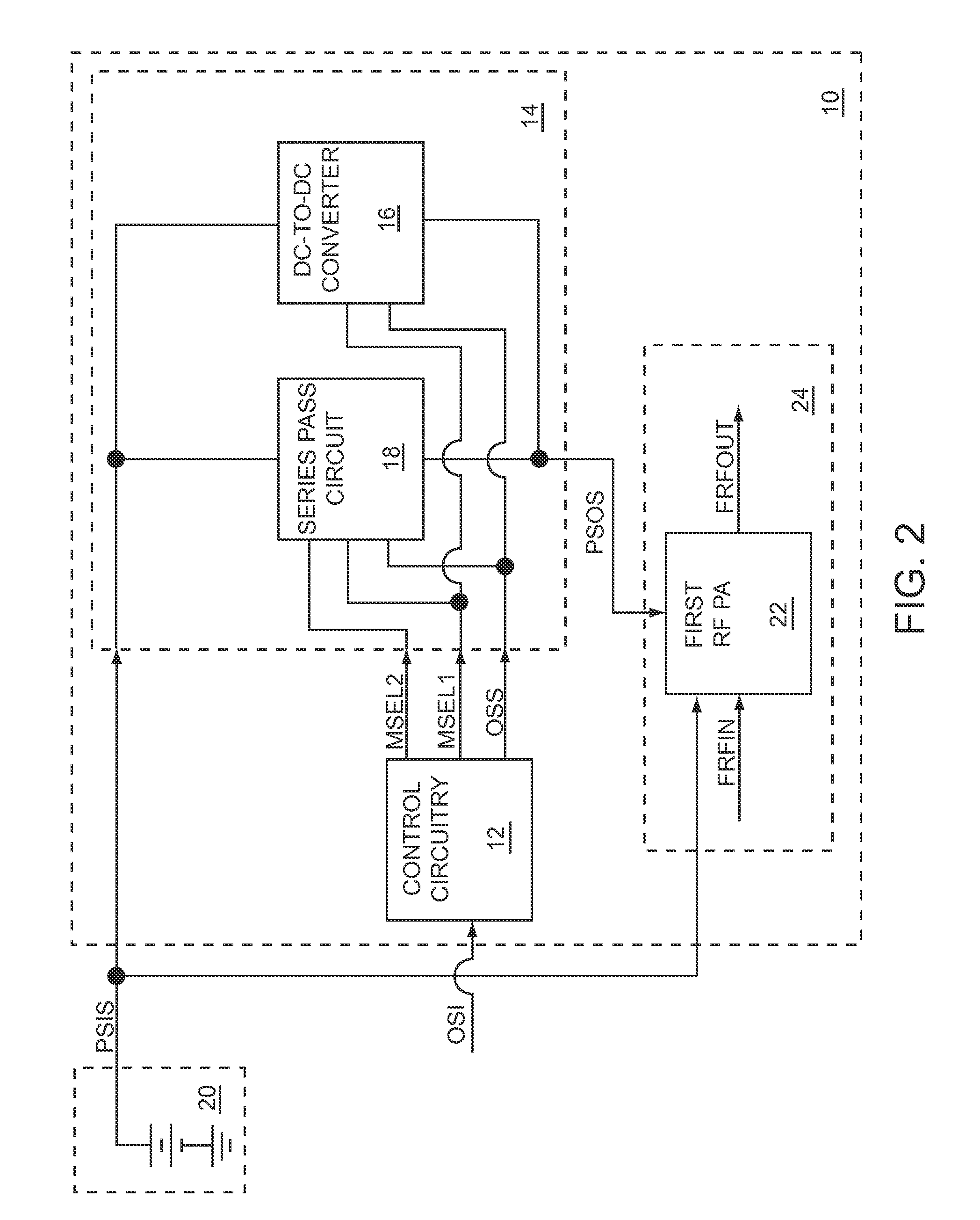
second embodiment
[0044]In the DC-to-DC converter 16, the switching circuitry 46 includes multiple capacitive elements (not shown), which are used as energy transfer elements to provide the switching circuitry output signal SCOS during the switching supply operating mode. Specifically, the capacitive elements may receive energy using the power supply input signal PSIS and transfer energy to the switching circuitry output signal SCOS. In an exemplary embodiment of the DC-to-DC converter 16, two capacitive elements (not shown) are used as energy transfer elements to provide the switching circuitry output signal SCOS during the switching supply operating mode.
[0045]Using inductive elements as energy transfer elements may have the benefit of providing good regulation of the switching circuitry output signal SCOS, which may minimize the voltage drop between the switching circuitry output signal SCOS and the power supply output signal PSOS, thereby maximizing efficiency. However, inductive elements may inc...
PUM
 Abstract
Description
Claims
Application Information