Substrate processing equipment

A substrate processing device and substrate technology, applied in the direction of conveyor control devices, transportation and packaging, electrical components, etc., can solve the problems of wrong detection of substrates, poor substrate transmission efficiency, and inability to transmit detection, so as to prevent false detection and realize processing Efficiency, the effect of improving transmission efficiency

Active Publication Date: 2016-05-04
SHIBAURA MECHATRONICS CORP
View PDF6 Cites 0 Cited by
  • Summary
  • Abstract
  • Description
  • Claims
  • Application Information

AI Technical Summary

Problems solved by technology

[0004] However, in the substrate processing apparatus described above, when the conveyed substrate collides with the detection roller and the swing member rotates, the swing member swings like a pendulum, and the swing motion of the swing member may not converge immediately.
Therefore, the reed switch detects the change of the magnetic field generated by the magnet many times, so there is a possibility of erroneously detecting the passage of the substrate
In addition, it takes time for the swing member to return to the converging position, so until the previous substrate is detected by the detection roller and the swing motion of the swing member converges, the next substrate cannot be transported and detected by touching the substrate with the detection roller.
Therefore, the substrate transfer interval at which the substrate transfer unit can transfer the substrate cannot be reduced, and the transfer efficiency of the substrate is poor, so the processing efficiency of the substrate cannot be improved.

Method used


Image

  • Substrate processing equipment
  • Substrate processing equipment
  • Substrate processing equipment

Examples


no. 1 Embodiment approach

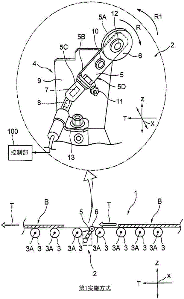
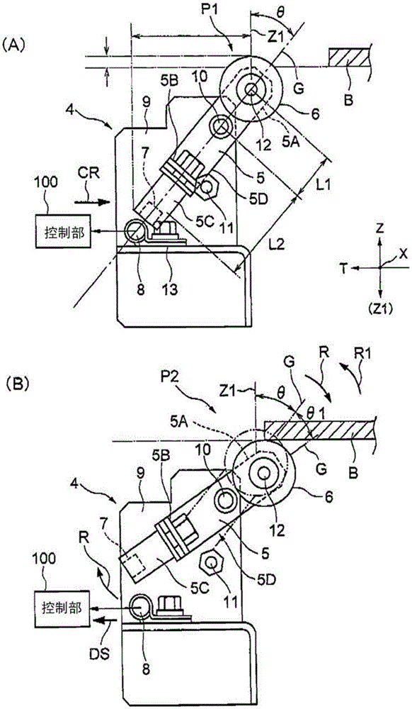
[0019] figure 1 It is a figure which shows the preferable 1st Embodiment of the substrate processing apparatus of this invention. figure 2 yes means figure 1 It is a diagram showing a configuration example and an operation example of the substrate inspection device 2 installed in the substrate processing apparatus shown.

[0020] Such as figure 1 As shown, in the embodiment of the present invention, as an example of a substrate processing apparatus, a substrate to be processed, such as a glass substrate B (hereinafter referred to as a substrate) for a liquid crystal display device, is conveyed along the conveying direction T, and the The cleaning treatment liquid is supplied to the front and back sides, and the stains on the surface of the substrate B are cleaned. As the cleaning treatment liquid, for example, pure water is used, but not limited thereto.

[0021] figure 1 The substrate processing apparatus 1 illustrated in FIG. 1 includes a substrate detection device 2 ,...

no. 2 Embodiment approach

[0046] Next, a preferred second embodiment of the substrate processing apparatus of the present invention will be described.

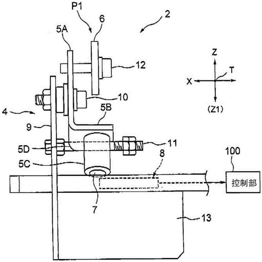
[0047] Figure 7 (A) is a front view showing the substrate detection device 102 included in the substrate processing device according to the second embodiment of the present invention, Figure 7 (B) is viewed from the arrow HJ Figure 7 (A) is a side view of the substrate processing apparatus 102 shown.

[0048] The substrate detection device 102 is also referred to as a substrate presence / absence detection device. The substrate inspection device 102 is set, for example, at figure 1 Between the conveyance roller 3 of the several conveyance roller 3 of the shown substrate processing apparatus 1, two adjacent conveyance rollers 3 are shown. Such as Figure 7(A) and Figure 7 As shown in (B), the substrate detection device 102 has a base 104, a swing member 105, a counterweight 105C, an additional counterweight 105D, a detection roller 106, a magnet...

no. 3 Embodiment approach

[0059] Next, a preferred third embodiment of the substrate processing apparatus of the present invention will be described.

[0060] Figure 8 It is a front view showing the substrate inspection device 202 included in the substrate processing apparatus according to the third embodiment of the present invention. Figure 8 The structure of the substrate detection device 202 shown is the same as Figure 7 (A) and Figure 7 The substrate inspection device 102 shown in (B) has substantially the same configuration, but has the following differences.

[0061] Such as Figure 8 As shown, there are base 104, swing member 105, counterweight 105C, forcing counterweight 105D, detection roller 106, magnet 107, detection sensor 108 such as reed switch, swing fulcrum member 110 and swing stopper 111. The swing member 105 has the Figure 7 The first portion 105S formed along the vertical line Z1 in the Z direction and the second portion 105T formed along the inclined line V in a state po...


PUM


Abstract

PROBLEM TO BE SOLVED: To provide a substrate processing device which can prevent erroneous detection of passage of a substrate by shortening convergence of an oscillating movement of an oscillating member and improve processing efficiency of the substrate by reducing an interval of substrate transfer and increasing transfer efficiency of the substrate.SOLUTION: A substrate detection device 2 of a substrate processing device 1 includes: a detection roller 6 on one end portion of an oscillating member 5; a weight 5C and a magnet 7 on the other end portion of the oscillating member 5; a detection sensor 8 which outputs a detection signal DS by detecting the change in a magnetic field generated by the magnet 7 when the oscillating member 5 is rotated in a rotation direction R from an initial position P1 of the oscillating member before a substrate B contacts the detection roller 6; and an oscillation stopper 11 which contacts the oscillating member 5 in order to maintain a state in which the oscillating member 5 is held obliquely with respect to a vertical line Z1 at the initial position P1 of the oscillating member 5. At the initial position P1 of the oscillating member 5, the oscillating member 5 is held obliquely with respect to the vertical line Z1.

Description

technical field [0001] Embodiments of the present invention relate to a substrate processing apparatus for transferring and processing substrates such as glass substrates of liquid crystal display devices. Background technique [0002] When manufacturing a glass substrate for a display device such as a liquid crystal display device, the substrate is conveyed in a substrate processing apparatus and various processes are performed on the substrate. The processing performed on the substrate by the substrate processing apparatus includes, for example, resist coating processing, resist stripping processing, etching processing, and cleaning processing. For example, when a substrate processing apparatus performs a cleaning process on a substrate, a cleaning treatment liquid is supplied to the surface of the substrate while the substrate is being transported by the substrate transport unit. [0003] Such a substrate processing apparatus has a substrate detection device that detects...

Claims


Application Information

Patent Timeline
Patent Type & Authority Patents(China)
IPC IPC(8): H01L21/677H01L21/66H01L21/67H01L21/68
CPCH01L21/67706H01L22/10B65G43/08H01L21/67276
Inventor 末吉秀树宫迫久显荻原洁滨田崇广
Owner SHIBAURA MECHATRONICS CORP
Why Eureka
Try Eureka