S-type passive micro-mixer

A mixer, passive technology, applied in mixers, laboratory utensils, chemical instruments and methods, etc., can solve the problems of poor mixing effect, shortened mixing distance, long mixing flow channel, etc., to achieve simple structure and reduce flow loss. , the effect of high mixing efficiency

Inactive Publication Date: 2014-03-19
JIANGSU UNIV
View PDF4 Cites 20 Cited by
  • Summary
  • Abstract
  • Description
  • Claims
  • Application Information

AI Technical Summary

Problems solved by technology

[0005] The purpose of the present invention is to solve the shortcomings of existing mixers such as long mixing time, long mixing channel, large flow loss, and poor mixing effect, and propose an S-type

Method used


Image

  • S-type passive micro-mixer
  • S-type passive micro-mixer
  • S-type passive micro-mixer

Examples


Embodiment Construction

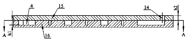
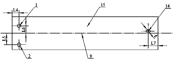
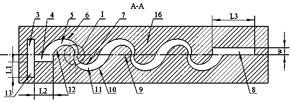
[0014] Such as Figure 1~4 As shown: the present invention includes an upper cover plate 15 and a mixing plate 16 that is positioned under the upper cover plate 15 and is bonded together with the upper cover plate 15, and the upper cover plate 15 is provided with an inlet hole one 1, an inlet hole two 2, Outlet hole 14, these three holes are all vertical through holes, all have a diameter of d, and a height of h2, which is equal to the height of the upper cover plate 15. The first inlet hole 1 and the second inlet hole 2 are located on the left side of the upper cover plate 15 , and the outlet hole 14 is located on the right side of the upper cover plate 15 . The polar axis 9 is a horizontal axis from left to right, and is the polar axis of the logarithmic helix in the mixing plate 16. The polar axis 9 is located on the vertical center plane where the upper cover plate 15 and the mixing plate 16 are located. The distance between the center of the inlet hole 1 and the inlet ho...


PUM


Abstract

The invention discloses an S-type passive micro-mixer in the microfluid mixing field, which comprises an upper cover plate and a mixing plate bonded together in an up-and-down manner; a first fluid inlet pipe, and a second fluid inlet pipe are disposed at the left side of the mixing plate; an outlet pipe is disposed at the right side; the two fluid inlet pipes are connected together with a main channel; n contraction mixing units and n diffusion mixing units orderly connected end to end in a smooth transition manner are disposed between the main channel and the outlet pipe; the first one of the n contraction mixing units is connected with the main channel, and the last diffusion mixing unit is connected with the outlet pipe; the outline of the horizontal axis cross section of a single contraction mixing unit is formed by two logarithmic spirals of the single contraction mixing unit; the outline of the horizontal axis cross section of a single diffusion mixing unit is formed by two logarithmic spirals of the single diffusion mixing unit; all the diffusion mixing units are at the front side of the polar axis of the logarithmic spiral, and all the contraction mixing units are at the back side of the polar axis; the contact area between fluids is increased, and thus mixing is more sufficient.

Description

technical field [0001] The invention relates to the microfluidic field of microfluidic mixing, in particular to a micromixer. Background technique [0002] The microfluidic system can realize the separation, sample addition, mixing, reaction, detection and other functions of the traditional biochemical detection process on the chip. This not only saves reagents, but also reduces dangers (such as toxic or violently reactive reagents). As an emerging technology, microchemical engineering can be used for analysis and comprehensive applications. Microreaction systems involved in microchemical engineering mainly include micromixers, microheat exchangers, and microchannels. Among them, micromixers have many problems: due to the scale The ratio of the surface area to the volume of the fluid in the microchannel of the micromixer is quite large, the flow rate and Reynolds number of the liquid are low, and it is often in a state of laminar flow. Mixing is often a diffusion movement ...

Claims


Application Information

Patent Timeline
IPC IPC(8): B01F13/00B01L3/00
Inventor 何秀华韦丹丹邓志丹杨嵩
Owner JIANGSU UNIV
Why Eureka
Try Eureka