A high-infrared curing device and method for brake pad steel back

A technology of infrared curing and brake pads, which is applied to the surface coating liquid device, pretreatment surface, coating, etc., can solve the problems of high energy consumption, difficult control of precision, low curing process efficiency of the brake pad steel back curing device, etc. Problems, achieve reasonable curing time, adjust curing time, improve curing quality and production efficiency

Active Publication Date: 2015-09-23
HUBEI CHIBI SALFER FRICTION MATERIAL
View PDF6 Cites 0 Cited by
  • Summary
  • Abstract
  • Description
  • Claims
  • Application Information

AI Technical Summary

Problems solved by technology

[0003] The technical problem to be solved by the present invention is to provide a high-infrared curing device and method for the steel back of the brake pad, which solves the problem of low efficiency, difficult control of precision, and large energy consumption in the curing device and curing process of the steel back of the brake pad in the prior art. technical issues

Method used


Image

  • A high-infrared curing device and method for brake pad steel back
  • A high-infrared curing device and method for brake pad steel back

Examples


Embodiment 1

[0029] The high infrared curing method of the present embodiment may further comprise the steps:

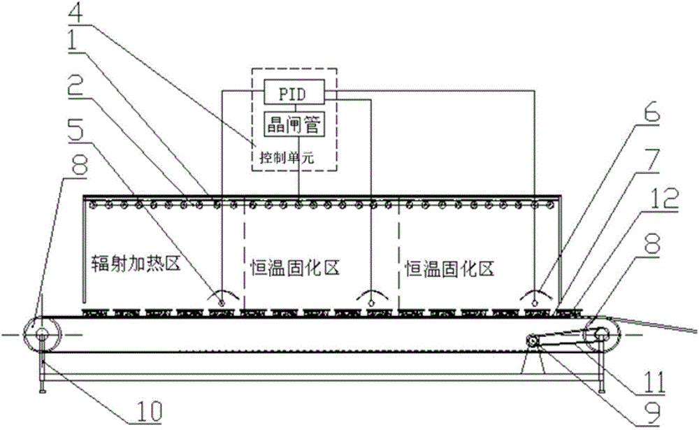
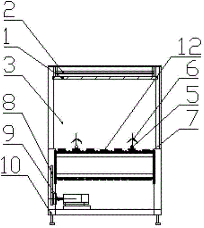
[0030] Step 1: Turn on the high-infrared radiator 1 and the temperature control system of the high-infrared curing device, respectively set the constant temperature to be reached in the radiation heating zone in the curing chamber 3 to 170°C, and the two constant-temperature curing zones require The achieved constant temperature is 200°C, and the control accuracy of the temperature sensor is ±1°C;

[0031] Second step: start the speed-regulating motor 9 of the metal chain belt conveyor, and the running speed of the metal mesh conveyor belt 7 is controlled at 5 meters per minute;

[0032] The third step: when the temperature of the radiation heating zone and the constant temperature curing zone reach the constant temperature, the brake pad is placed on the running metal mesh conveyor belt 7, and the friction material part of the brake pad faces placed downwards, the part of the s...

Embodiment 2

[0034] The steps of this embodiment are basically the same as those of Embodiment 1, the difference is that: the set temperature of the radiation heating zone in the curing chamber 3 is 190°C, the set temperature of the two constant temperature curing zones is 220°C, and the control accuracy is ±1°C; The running speed of the metal mesh conveyor belt 7 is 6 m / min.

Embodiment 3

[0036] The steps of this embodiment are basically the same as those of Embodiment 1, the difference is that: the set temperature of the radiation heating zone in the curing chamber 3 is 180°C, the set temperature of the two constant temperature curing zones is 210°C, and the control accuracy is ±1°C; The running speed of the metal mesh conveyor belt 7 is 5.5 m / min.

[0037]A high-infrared curing device and method for the steel back of the brake pad according to the present invention, the curing device has a simple structure, a high degree of temperature control automation, fast curing speed, and low energy consumption; Spray curing, high production efficiency, high product quality, and effectively reduce production costs.


PUM


Abstract

The invention relates to a high-infrared curing device and method for a brake pad steel back. The high-infrared curing device comprise a conveyor, a high-infrared radiator, a radiator support, a curing chamber and a temperature control system, the conveyor is provided with a frame and a metal mesh conveying belt for conveying brake pads, the metal mesh conveying belt and the frame positioned above the metal mesh conveying belt enclose a space to form the curing chamber, the radiator support is fixed on the frame at the top of the curing chamber, the high-infrared radiator is mounted on the radiator support, and the temperature control system adjusts the power of the high-infrared radiator according to the temperature of the curing chamber, so that the temperature of the curing chamber reaches and keeps the preset constant temperature. The curing device is simple in structure, high in temperature control automation degree, fast in curing, low in energy consumption, the curing method is high in production efficiency, product quality is high, and production cost can be effectively reduced.

Description

technical field [0001] The invention relates to a curing device and method, in particular to a high-infrared curing device and method for steel backs of brake pads. Background technique [0002] In the surface spraying process of the steel back of the brake pad, the traditional heating equipment mainly heats the heat pipe and bakes the surface of the workpiece in the baking furnace. The heat can only be slowly transferred from the surface to the inside of the coating. Therefore, the curing The speed is slow, the production efficiency is low, the energy consumption is large, and the curing quality of the workpiece surface is poor. With the application of infrared heating technology in the field of surface spraying, the curing speed and work efficiency of the workpiece have been greatly improved. However, ordinary opalescent glass infrared heating tubes do not evacuate, and have large thermal inertia, resulting in low temperature control accuracy, low thermal efficiency, and ...

Claims


Application Information

Patent Timeline
Patent Type & Authority Patents(China)
IPC IPC(8): B05D3/02B05C13/02
Inventor 郭东辉程时忠李军郭江波郭正刚
Owner HUBEI CHIBI SALFER FRICTION MATERIAL
Why Eureka
Try Eureka