Turnover-type thermal shock and thermal fatigue test platform

A test platform and thermal shock technology, applied in the testing of mechanical components, testing of machine/structural components, measuring devices, etc., can solve the problems affecting the reliability and durability of the whole machine, the decrease of reliability and life, and the lack of thermal strength of materials and other problems, to achieve the effect of saving test costs, increasing the ambient temperature, and shortening the test cycle

Active Publication Date: 2018-04-06
KUNMING UNIV OF SCI & TECH
View PDF8 Cites 5 Cited by
  • Summary
  • Abstract
  • Description
  • Claims
  • Application Information

AI Technical Summary

Problems solved by technology

The increase of the explosion pressure increases the heat load of the piston, cylinder head, exhaust pipe, turbine, and cylinder liner, resulting in greater thermal stress and thermal deformation. Under the action of the heat load, the piston, cylinder head, and exhaust pipe of the engine , The strength and hardness of the turbine and cylinder liner materials have dropped sharply, which has reduced their reliability and life, and are more prone to cracks, cracks, and even fractures. When these heated parts do not make corresponding technical improvements or improvements Improper, such as unreasonable structural design, insufficient cooling capacity, insufficient thermal strength of materials, etc., these heated parts will not meet the requirements of use and will seriously affect the reliability and durability of the whole machine

Method used


Image

  • Turnover-type thermal shock and thermal fatigue test platform
  • Turnover-type thermal shock and thermal fatigue test platform

Examples


Embodiment 1

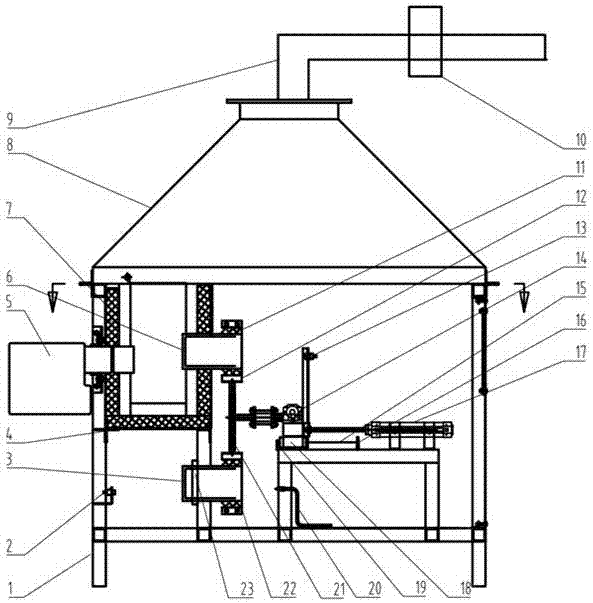
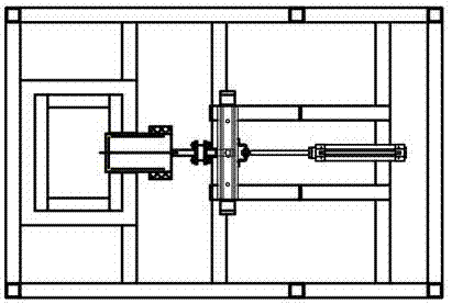
[0019] Embodiment 1: as Figure 1-2 As shown, a flip-type thermal shock and thermal fatigue test platform includes a test bench support 1, an infrared thermometer I2, a test piece I3, a heat preservation chamber support 4, a heating device 5, a test piece II6, a heat preservation chamber 7, a smoke Cover 8, smoke exhaust pipe 9, high temperature pipe exhaust fan 10, fixture I12, infrared thermometer II13, swing cylinder 14, linear guide rail 15, position sensor I16, linear cylinder 17, slider 18, position sensor II19, infrared temperature measurement Instrument III20, T-bar 21, fixture II22, cooling device 23, controller;

[0020] Infrared thermometer 12 and heating device 5 are inlaid on the wall surface of described test bench support 1, and heating device 5 is positioned at infrared thermometer 12 top, and heat preservation cavity 7 is fixed on the test bench support 1 by heat preservation cavity support 4, and heating device 5 One end of the T-bar extends into the heat pr...


PUM


Abstract

The invention relates to a turnover-type thermal shock and thermal fatigue test platform, which belongs to the technical field of test appliances. The turnover-type thermal shock and thermal fatigue test platform comprises a test platform support, a first infrared thermometer, a first test piece, a heat preservation cavity support, a heating device, a second test piece, a heat preservation cavity,a hood, an exhaust manifold, a high-temperature pipe fan, a first clamp, a second infrared thermometer, a swing cylinder, a linear guide rail, a first position sensor, a linear cylinder, a sliding block, a second position sensor, a third infrared thermometer, a T-type rod, a second clamp, a cooling device and a controller. Two test pieces can be tested at the same time, one is heated and the other one is cooled, the two test pieces turn over vertically for 180 DEG under driving of the swing cylinder, and the two test pieces can rotate together with a working platform to exchange working positions under driving of the swing cylinder. The turnover-type thermal shock and thermal fatigue test platform is simple, practical and high in working efficiency, and in the case of simulated experimental study on thermal shock and thermal fatigue of a piston in an internal combustion engine, the test cost can be saved, and the research and development period of related parts can be greatly shortened.

Description

technical field [0001] The invention relates to a flip-type thermal shock and thermal fatigue test platform, which is applied to a test platform for strength assessment of mechanical heated parts and belongs to the technical field of test supplies. Background technique [0002] The automobile industry is one of the most important industries in economically developed countries, and the heart of the automobile is the internal combustion engine. With the rapid development of science and technology, the engine is developing in the direction of high power and high speed. With the continuous increase of engine speed and power, combustion chamber Burst pressure and temperature will continue to increase. The increase of the explosion pressure increases the heat load of the piston, cylinder head, exhaust pipe, turbine, and cylinder liner, resulting in greater thermal stress and thermal deformation. Under the action of the heat load, the piston, cylinder head, and exhaust pipe of the ...

Claims


Application Information

Patent Timeline
IPC IPC(8): G01M13/00
CPCG01M13/00
Inventor 雷基林邓晰文王东方贾德文毕玉华申立中
Owner KUNMING UNIV OF SCI & TECH
Why Eureka
Try Eureka