Lower die structure of magnetic-conducting piece blanking die
A technology for blanking molds and magnetic conductive sheets, which is used in manufacturing tools, metal processing equipment, peeling devices, etc., can solve the problems of high cost of precision machine tools and molds, jamming of upper molds, and inability to fully guarantee processing accuracy requirements. Improve section finish and accuracy, avoid jamming, and achieve uniform gaps
- Summary
- Abstract
- Description
- Claims
- Application Information
AI Technical Summary
Problems solved by technology
Method used
Image

Examples
Embodiment Construction
[0013] The invention will be further described in detail below in conjunction with the accompanying drawings and specific embodiments.
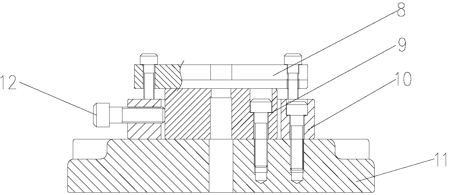
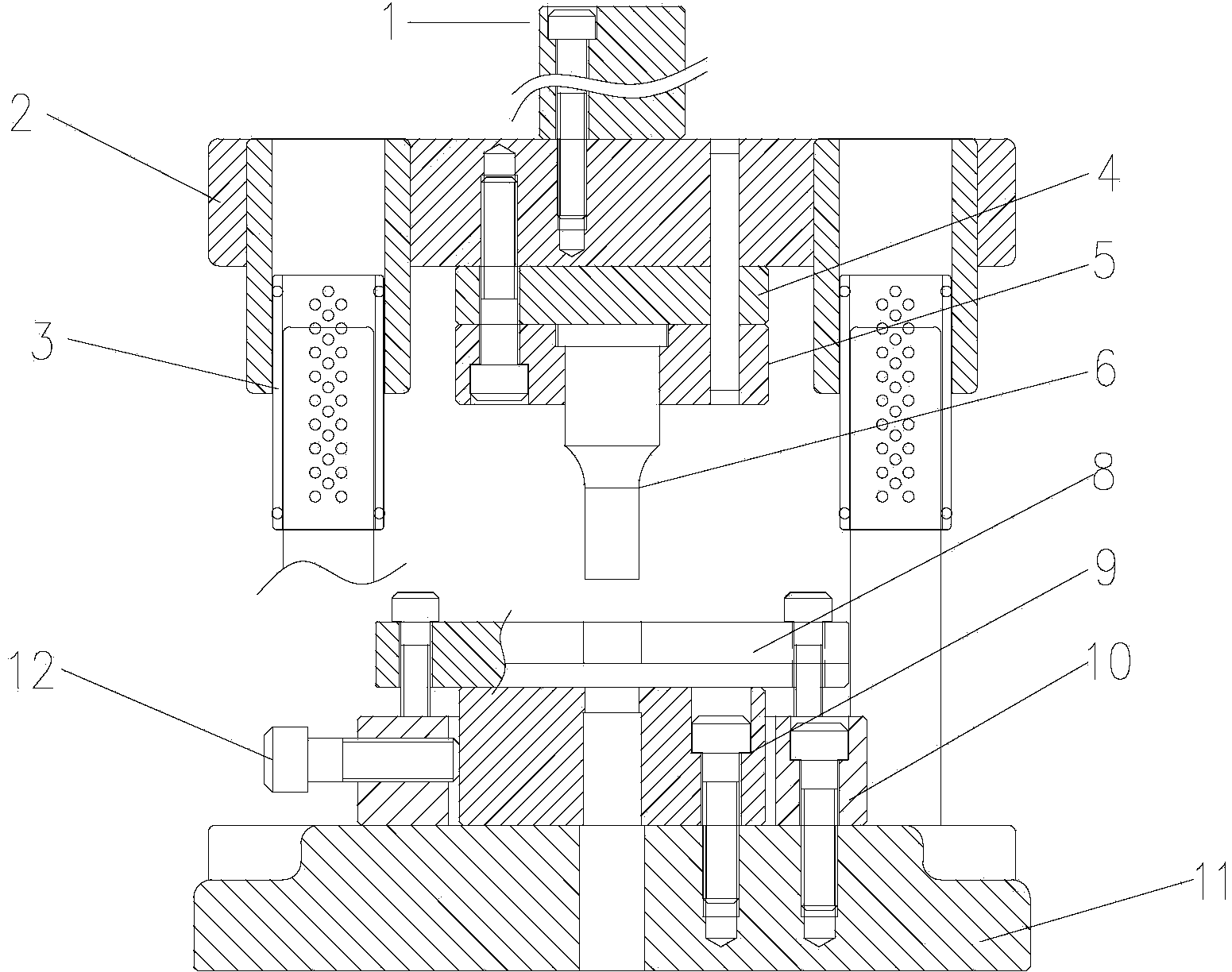
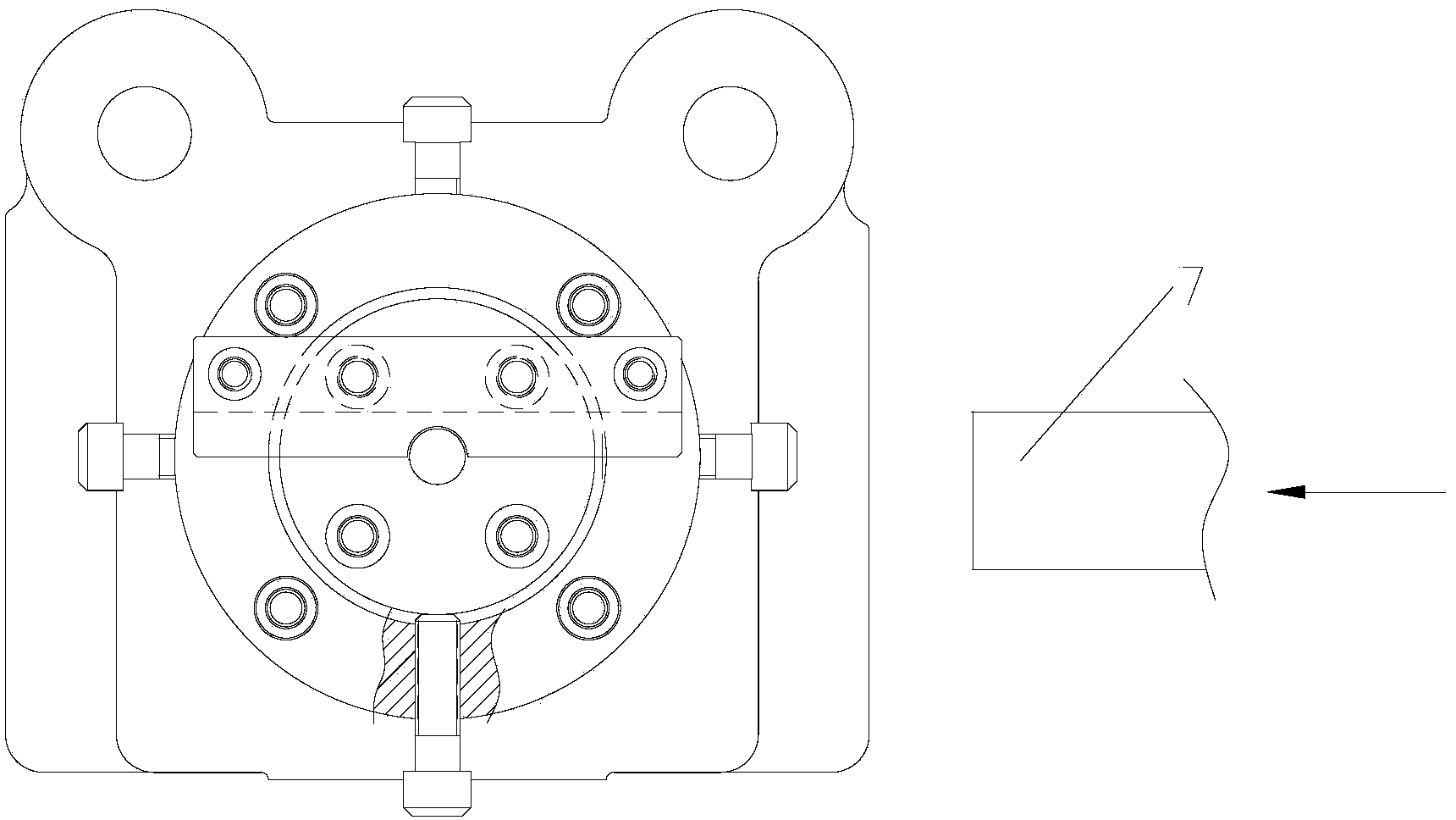
[0014] refer to figure 1 As shown, the lower mold structure of a magnetic sheet blanking mold provided by the invention includes a die 9 and a lower template 11, wherein the die 9 is installed on the lower template 11, and the present invention also includes a die installed on the lower template 11 is used to adjust the adjustment mechanism for adjusting the horizontal displacement of the die 9, and the stripping mechanism that is located at the upper end of the die 9 for stripping after stamping. Like this, the present invention adopts adjustment mechanism to adjust the horizontal displacement of die on the one hand, can make the gap between the die 9 of the whole mold and the punch uniform, to improve the cross-section smoothness and precision of blanking magnetic conductive sheet, on the other hand The unloading mechanism is used for unlo...
PUM
 Abstract
Description
Claims
Application Information
PatSnap Eureka turns technology decisions into work you can execute. Powered by our Innovation Knowledge Graph, it runs expert workflows across engineering, life sciences, materials and intellectual property. Get your review-ready output in minutes.


