Die cleaning line, die cleaning equipment and die cleaning method for tubular piles

A mold cleaning and equipment technology, applied in the direction of ceramic molding machines, manufacturing tools, etc., can solve the problems of unsuitable concrete pipe pile mold cleaning, mold cleaning process needs to be further improved, and is not conducive to reducing production costs, so as to avoid the influence of subjective factors , improve safety, and ensure the effect of mold cleaning process

Active Publication Date: 2014-03-19
GUANGDONG SANHE PILE CO LTD
View PDF8 Cites 9 Cited by
  • Summary
  • Abstract
  • Description
  • Claims
  • Application Information

AI Technical Summary

Problems solved by technology

[0006] 1. Multiple mold-cleaning steel brush wheels adopt a parallel design. The lifting motor drives multiple mold-cleaning steel brush wheels to rise and fall together. Turn on the drive motor to make the mold-cleaning equipment move horizontally back and forth on the track. This structural design makes the mold-cleaning equipment Multiple mold cleaning steel brush wheels can only gradually clean the mold with small fluctuations on the surface of the cavity, and it is difficult to clean the mold with large fluctuations on the surface of the cavity
[0007] 2. The concrete is directly removed by the steel brush wheel for mold cleaning. The steel brush wheel for mold cleaning rotates at high speed, which is easy to scratch the mold. The quality of mold cleaning is not high, and the mold cleaning process needs to be further improved. The mold steel brush wheel throws up the concrete dust and splashes it around, polluting the surrounding environment and equipment, affecting the service life of the equipment, increasing the maintenance cost of the equipment, and not conducive to reducing the production cost
[0008] 3. Since the structure of concrete pipe piles is different from that of concrete wall panels, the above mold cleaning equipment is suitable for cleaning concrete wall panel molds, but not suitable for cleaning concrete pipe pile molds

Method used


Image

  • Die cleaning line, die cleaning equipment and die cleaning method for tubular piles
  • Die cleaning line, die cleaning equipment and die cleaning method for tubular piles
  • Die cleaning line, die cleaning equipment and die cleaning method for tubular piles

Examples


Embodiment Construction

[0043] The present invention will be further described below in conjunction with specific embodiment:

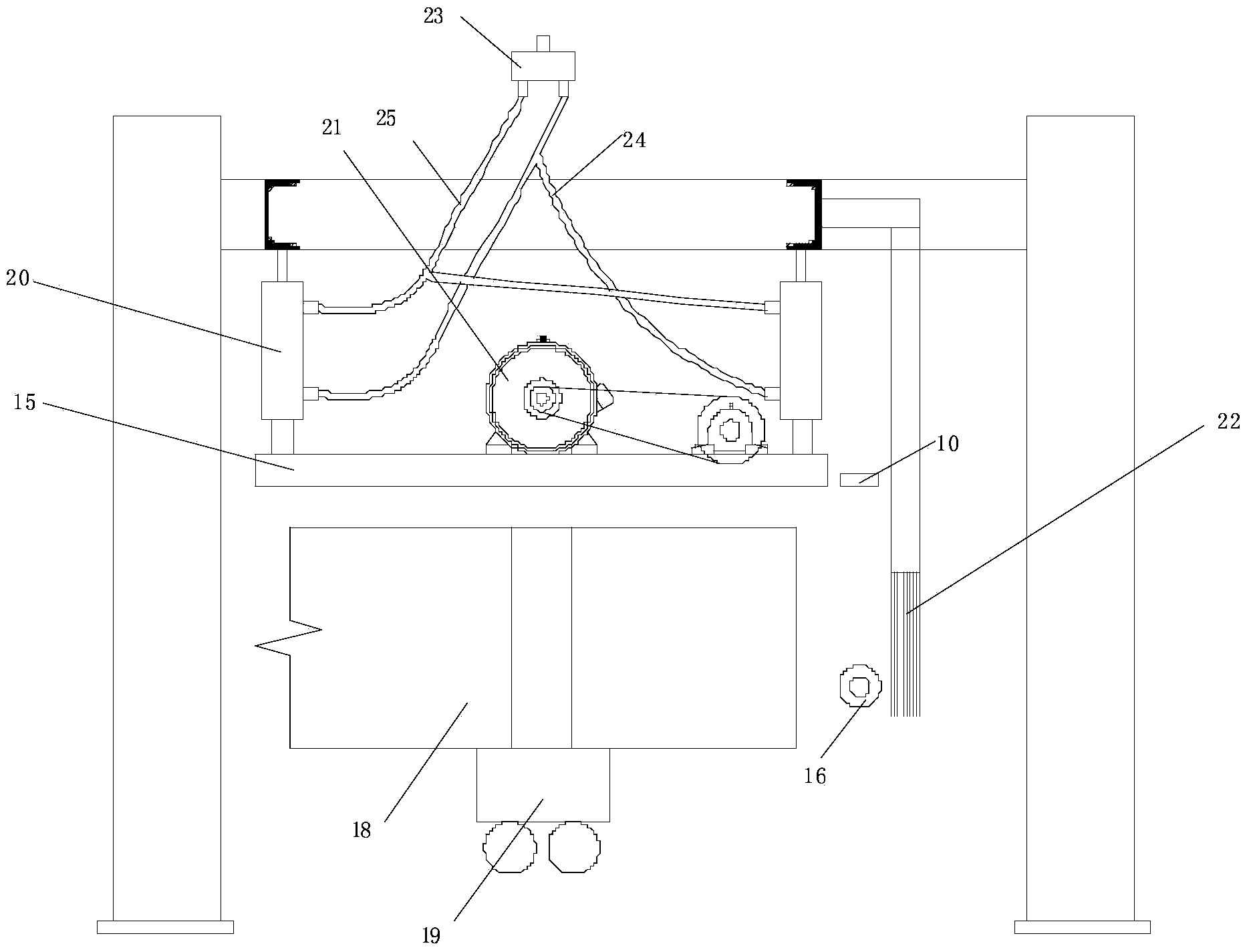
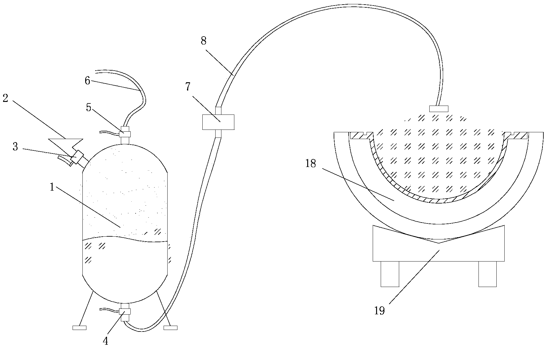
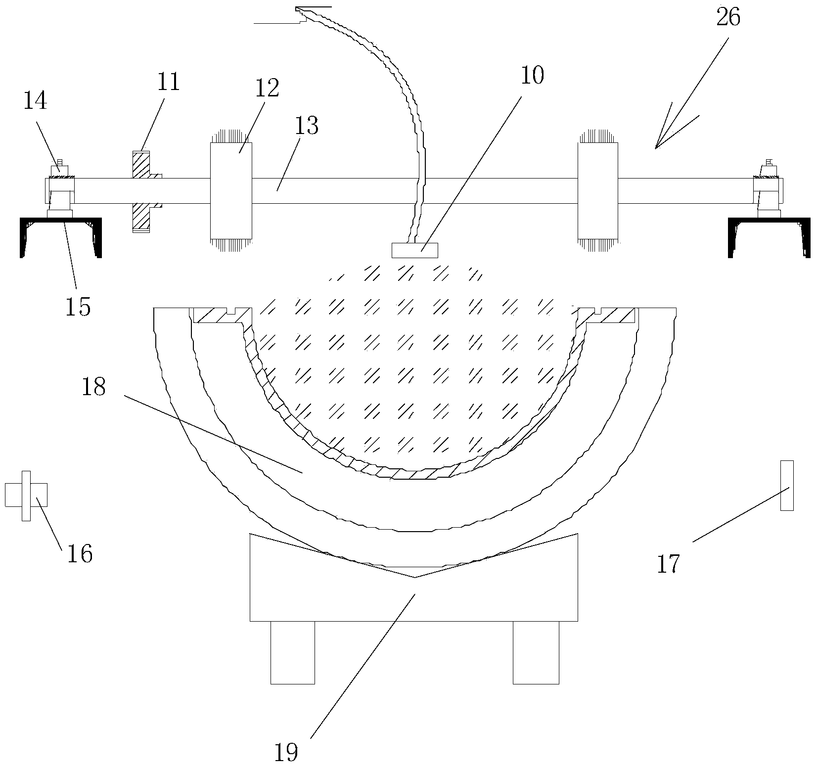
[0044] Such as figure 1 , figure 2 , image 3 and Figure 4 As shown, a pipe pile mold cleaning circuit includes mold release agent spraying equipment, mold cleaning equipment, pipe mold conveying equipment and a photoelectric switch, the discharge nozzle 10 of the photoelectric switch, mold release agent spraying equipment and mold cleaning equipment along the pipe mold The conveying equipment 19 is set in sequence before and after the moving direction; the release agent spraying equipment is provided with a first electronically controlled valve 7 that controls the release nozzle 10 on and off;

[0045] The mold cleaning equipment includes a bracket 9, a lifting device 20, a notch cleaner 26 and an inner chamber cleaner 22, the notch cleaner 26 and the inner chamber cleaner 22 are set up and down, and the inner chamber cleaner 22 is located directly above the pipe mold,...


PUM


Abstract

The invention relates to a die cleaning method for tubular piles, which comprises the following steps: step 1, a photoelectric switch, release agent spraying equipment and die cleaning equipment are arranged in the pipe die moving direction from the front to the back in sequence; step 2, the photoelectric switch is cut off when a pipe die is detected, after the photoelectric switch is cut off, the release agent spraying equipment is started by an electrical signal to spray a release agent on the surface of a die cavity of the die, and meanwhile, the die cleaning equipment is start to enter a working state from a standby state; step 3, the pipe die moves forwards to be sprayed with the release agent gradually and cleaned by the die cleaning equipment gradually; step 4, when the photoelectric switch is switched on again, the release agent spraying equipment stops spraying, and the die cleaning equipment stops die cleaning and is reset to enter the standby state. The invention aims to provide a die cleaning line, the die cleaning equipment and the die cleaning method for the tubular piles, which have the advantages of simplicity and convenience in operation, low labor intensity, high degree of automation and high die cleaning quality.

Description

technical field [0001] The invention relates to a mold cleaning machine and a mold cleaning method, in particular to a pipe pile mold cleaning circuit, mold cleaning equipment and a mold cleaning method. Background technique [0002] With the development of concrete technology, the technology of concrete pipe piles is becoming more mature and more widely used. Correspondingly, pipe pile production equipment must keep up with the production rhythm, meet higher production process requirements, reduce labor intensity and continuously improve production efficiency. The problem. [0003] The production of concrete pipe piles needs to go through the mold cleaning process. In order to ensure the quality of pipe pile production, this is an indispensable part of the prestressed pipe pile production line. The labor intensity of workers in the traditional mold cleaning process is high, and the work efficiency is low, which can no longer meet the requirements of the pipe pile productio...

Claims


Application Information

Patent Timeline
Patent Type & Authority Applications(China)
IPC IPC(8): B28B7/38
CPCB28B7/386B28B7/388
Inventor 韦泽林谢宝山
Owner GUANGDONG SANHE PILE CO LTD
Why Eureka
Try Eureka