
Detection circuit and its vehicle inverter system

A technology for detection circuits and vehicles, which is applied in the direction of measuring electrical variables, measuring electricity, measuring devices, etc., can solve problems such as electric shock, fire, and potential safety hazards, and achieve the effect of eliminating potential safety hazards and saving wiring harness costs

Active Publication Date: 2016-07-20
KEBODA TECH CO LTD +2
View PDF5 Cites 0 Cited by
  • Summary
  • Abstract
  • Description
  • Claims
  • Application Information

AI Technical Summary

Problems solved by technology

Since the output of the inverter circuit 91 is a high-voltage AC voltage, if the high-voltage wire harness 94 is disconnected, it will lead to potential safety hazards, and may even cause electric shock or fire.

Method used


Image

  • Detection circuit and its vehicle inverter system
  • Detection circuit and its vehicle inverter system
  • Detection circuit and its vehicle inverter system

Examples


specific Embodiment approach

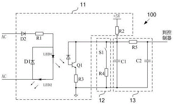
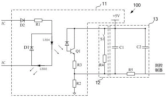
[0029] The series circuit includes a switch circuit S1 and a second resistor R4 connected in series. The switch circuit S1 is used to turn on or off according to the change of the external input; the series circuit is connected in parallel with the phototransistor Q1 and connected to the 5V power supply through the first resistor R2. Wherein, one end of the series circuit is connected to the collector of the phototransistor Q1, and the other end is connected to the emitter of the phototransistor Q1. Preferably, the emitter of the phototransistor Q1 is provided with a third resistor R3 as a pull-down resistor, the emitter of the phototransistor Q1 is connected to one end of the third resistor R3, and the other end of the third resistor R3 is connected to the series circuit. Both ends are grounded. The first resistor R2 can be as figure 2 shown, used as pull-up resistors, can also be used as image 3 As shown, it is used as a pull-down resistor. That is, after the aforement...


PUM


Abstract

The invention discloses a detection circuit. The detection circuit is applied to a voltage conversion device comprising a voltage conversion circuit and an output joint; the output end of the voltage conversion circuit is connected with the output joint; the detection circuit comprises an isolator and a series circuit; the isolator is used for detecting whether the voltage conversion circuit is disconnected with the output joint or not and comprises a power supply, a first resistor, a triggering element located on the primary edge and a triggered element located on the auxiliary edge; two ends of the triggering element are connected with the input end of the output joint; the series circuit comprises a switching circuit and a second resistor which are in series connection with each other; the switching circuit is used for connecting or disconnecting according to the change of the external input; the series circuit and the triggered element are connected with the power supply through the first resistor after being in parallel connection with each other. The invention also discloses an automotive inverter system with the detection circuit. According to the detection circuit, the change of the external input and the connection or the disconnection between the voltage conversion circuit and the output joint can be detected simultaneously, different detection signals can be outputted, and accordingly the voltage conversion circuit can be controlled by a follow-up control system conveniently.

Description

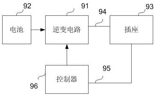
technical field [0001] The invention relates to a detection circuit and its vehicle inverter system. Background technique [0002] A voltage conversion system is a system that converts a source voltage into a demand voltage. With the development and progress of science and technology, voltage conversion systems have been widely used, and there are many types, such as AC-DC conversion systems, DC-DC conversion systems, and DC-AC inverter systems. While being widely used, people have also found that there are still many safety problems in the voltage conversion system. Taking the automotive inverter system as an example, figure 1 A functional block diagram of an inverter system for a vehicle is shown, wherein an input end of an inverter circuit 91 is connected to a battery 92 , and an output end is connected to a socket 93 through a high-voltage wire harness 94 . A micro switch (not shown in the figure) arranged in the socket 93 is connected to the input end of the controll...

Claims


Application Information

Patent Timeline
Patent Type & Authority Patents(China)
IPC IPC(8): G01R31/02H02M7/48
Inventor 阳彩梁风吴正海聂思贵
Owner KEBODA TECH CO LTD
Learn More