
Transparent and simulated teaching steam engine

A technology of simulation teaching and steam engine, applied in the field of teaching models, can solve the problems of low production precision requirements and low transparency of steam engine teaching aids, and achieves the effects of good balance, inspiring imagination and creative thinking, and reducing precision.

Inactive Publication Date: 2014-03-19
CHONGQING UNIVERSITY OF SCIENCE AND TECHNOLOGY
View PDF5 Cites 0 Cited by
  • Summary
  • Abstract
  • Description
  • Claims
  • Application Information

AI Technical Summary

Problems solved by technology

[0003] In view of the above-mentioned technical problems in the prior art, the purpose of the present invention is to provide a transparent, simulated teaching steam engine, which uses a vacuum cleaner or a blower to create an airflow to provide a power source and drive the steam engine to run; the steam engine has low requirements for manufacturing precision, and students can Participate in hands-on assembly to achieve the effect of teaching interaction; and all transmission structures and moving parts are external or transparent, which solves the technical problem of low transparency of steam engine teaching aids

Method used

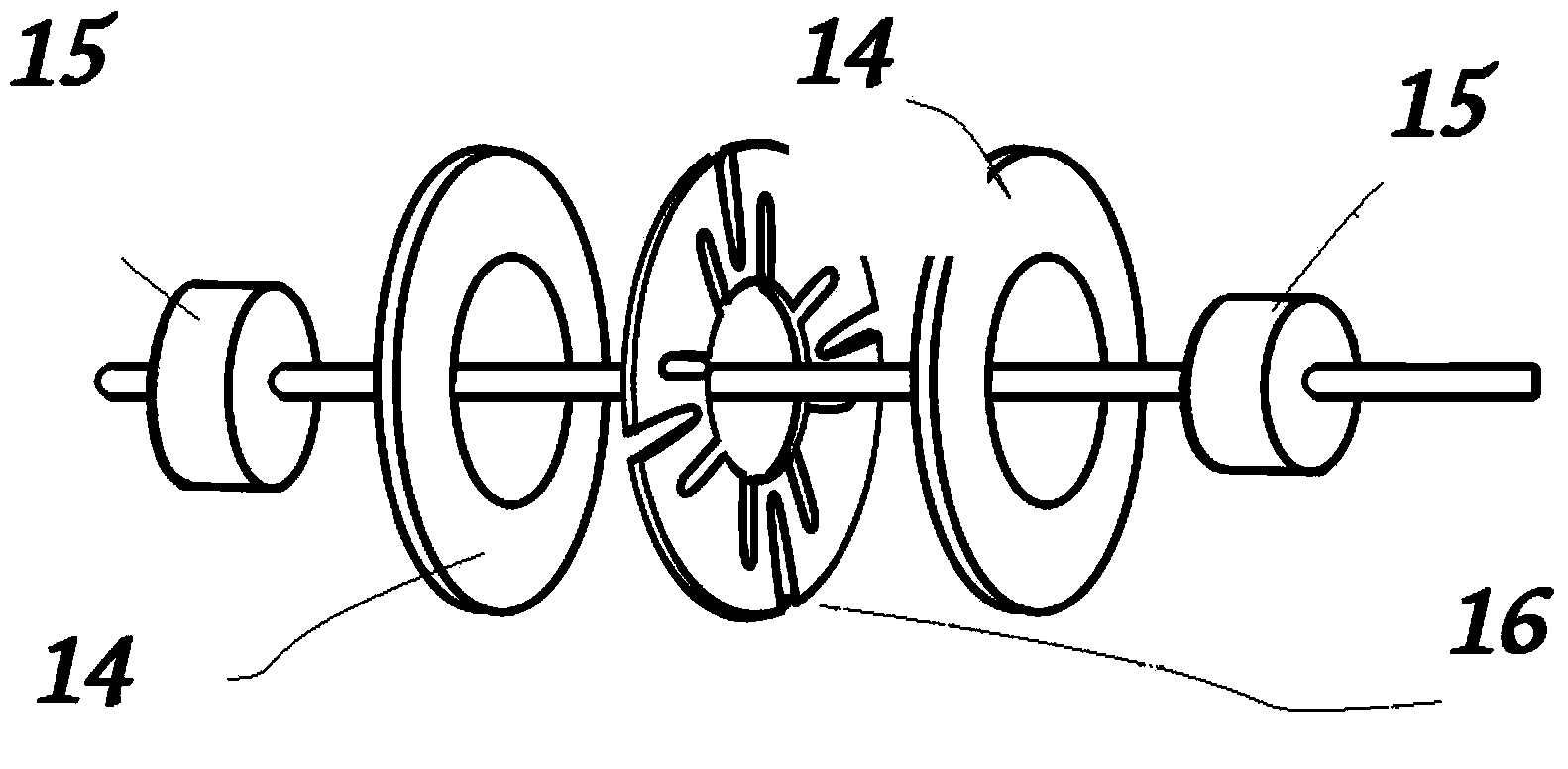
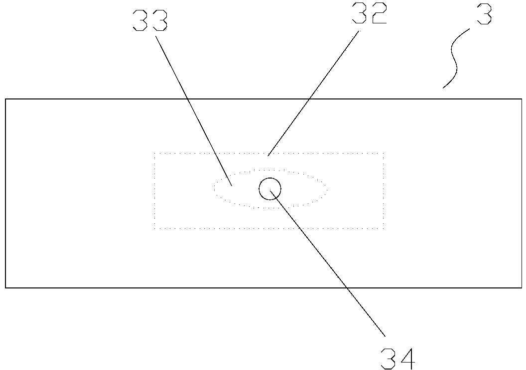

Image

  • Transparent and simulated teaching steam engine
  • Transparent and simulated teaching steam engine
  • Transparent and simulated teaching steam engine

Examples


Embodiment Construction

[0023] The specific implementation manner of the present invention will be described in further detail below in conjunction with the accompanying drawings.

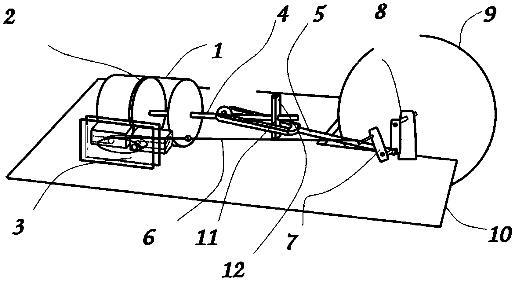
[0024] like figure 1 As shown, the transparent, simulated teaching steam engine of the present invention includes a base 10, a cylinder 1 fixedly arranged on the base 10, a piston 2 is arranged in the cylinder 1, and the piston 2 is connected to one end of the power connecting rod 4, and the power connecting rod 4 The other end of the cylinder 1 passes through the perforation 11, the perforation 11 is arranged on the perforation bracket 12, the power connecting rod 4 protrudes from the perforation 11 to have a certain length, and can move in the axial direction in the perforation 11; The fork end of the connecting rod 5 is flexibly connected with the power connecting rod 4, and the other end of the connecting rod 5 is connected to the simulated crank 7; the simulated crank 7 is arranged on one end of the rotating shaft 8,...


PUM


Abstract

The invention relates to a transparent and simulated teaching steam engine comprising a pedestal, an air cylinder, a piston. The piston is connected to one end of a power connecting rod; and the other end passes through the air cylinder and a penetrating hole of a penetrating hole support. A fork portion of a fork connecting rod is movably connected with the power connecting rod; and the other end is connected with a simulated crank. The simulated crack is arranged at one end of a rotating shaft and the other end of the rotating shaft is provided with a flywheel; and the rotating shaft is arranged at a support. Two vent holes are arranged in the side wall of the air cylinder and are used for air suction and exhausting; a flow dividing air valve is arranged at the outer side of the air cylinder; two openings, approaching the air cylinder, of the flow dividing air valve are respectively communicated with the two vent holes of the air cylinder; and an air inlet, far away from the other side of the air cylinder, of the flow dividing air valve is connected with an airflow source. A sliding block, which is arranged in the flow dividing air valve and is connected with a dividing connecting rod and the simulated crank, moves back and forth at the axial direction of the air cylinder under the driving of the simulated crank, so that the air flow is guided to enter the air cylinder through one opening of the flow dividing air valve and one vent hole of the air cylinder and thus the piston is pushed to make motion.

Description

technical field [0001] The invention relates to a teaching model, in particular to a transparent and simulated teaching steam engine model for demonstrating the structure and working principle of the steam engine to students. Background technique [0002] The steam engine has an indelible and important position in the history of human civilization and science and technology, so it is very important to let students understand the structure and working principle of the steam engine well in teaching. However, the existing steam engine teaching aids are not transparent enough, some important parts cannot be seen visually, and the teaching effect is compromised; at the same time, the production precision is high, the production cost is high, and it is not easy to popularize. Moreover, some steam engine teaching aids cannot be propelled by any gas at all, and can only be made into anatomical steam engines. The operation of the steam engine is displayed by manual or motor rotation,...

Claims


Application Information

Patent Timeline
Patent Type & Authority Applications(China)
IPC IPC(8): G09B25/02
Inventor 周鑑恒唐海燕
Owner CHONGQING UNIVERSITY OF SCIENCE AND TECHNOLOGY
Learn More