
RC reset circuit with power supply inspection and control function

A reset circuit and power supply technology, applied in electrical components, electronic switches, pulse technology, etc., can solve problems such as reduced system stability, unstable peripheral circuit status, and system work confusion

Inactive Publication Date: 2014-03-19
QINGDAO GOERTEK
View PDF7 Cites 3 Cited by
  • Summary
  • Abstract
  • Description
  • Claims
  • Application Information

AI Technical Summary

Problems solved by technology

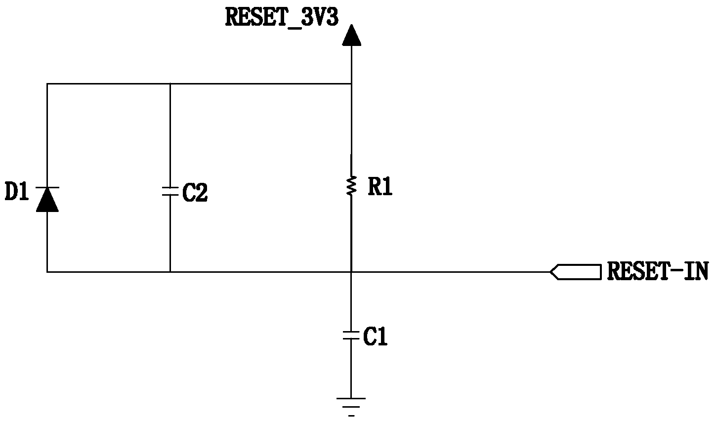
Since the existing RC reset circuit does not have the function of detecting and controlling the power supply voltage, when the power supply PWR_3V3 is still unstable at the initial stage of power-on, after the capacitor C1 is charged, the voltage of the reset input terminal RESET_IN rises, and the system that needs to be reset is reset; Moreover, the state of the peripheral circuit of the system that needs to be reset is also unstable. In this case, the system can easily cause work confusion, reduce the stability of the system, and cause unnecessary losses.

Method used


Image

  • RC reset circuit with power supply inspection and control function
  • RC reset circuit with power supply inspection and control function
  • RC reset circuit with power supply inspection and control function

Examples


Embodiment 1

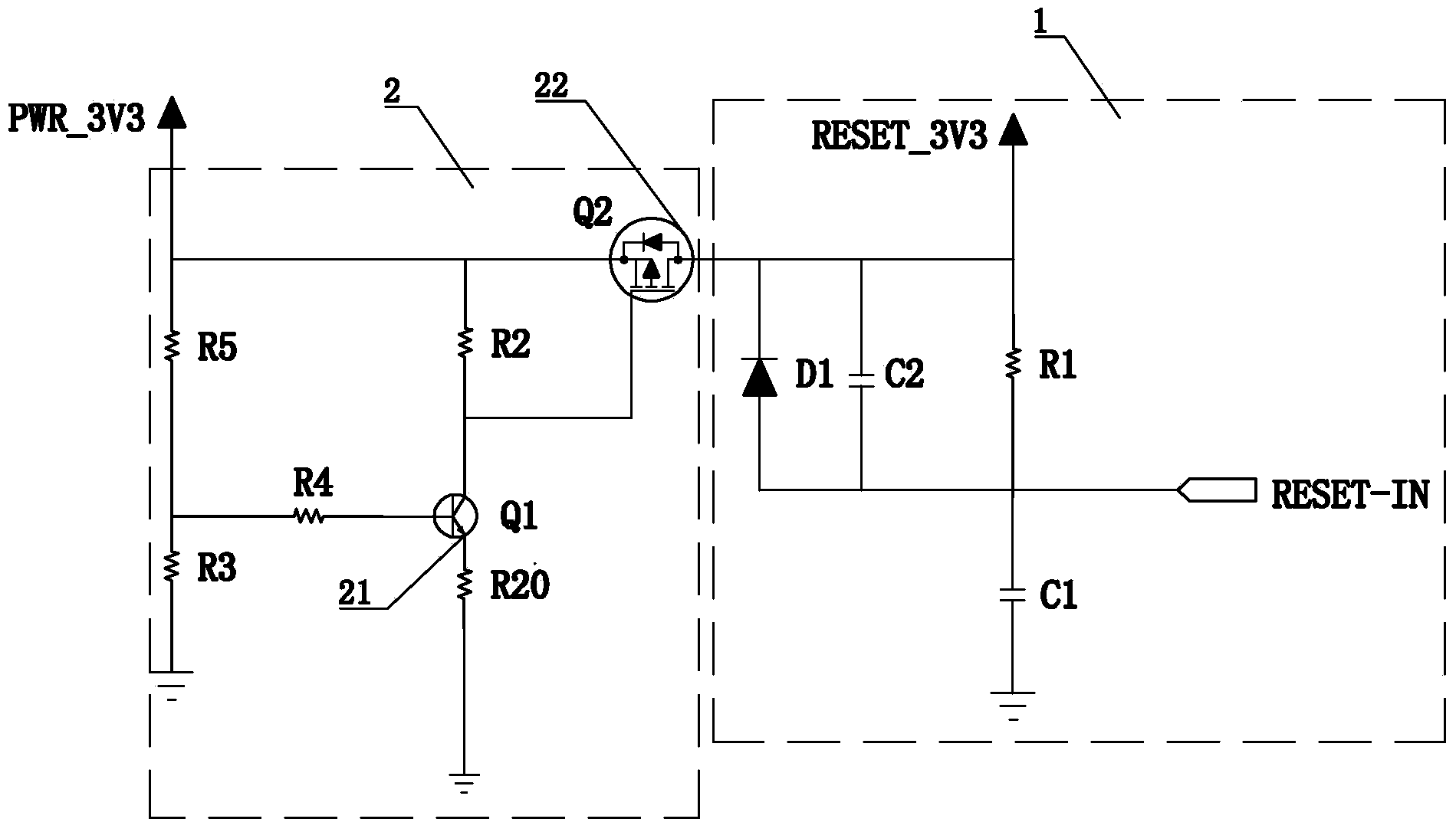
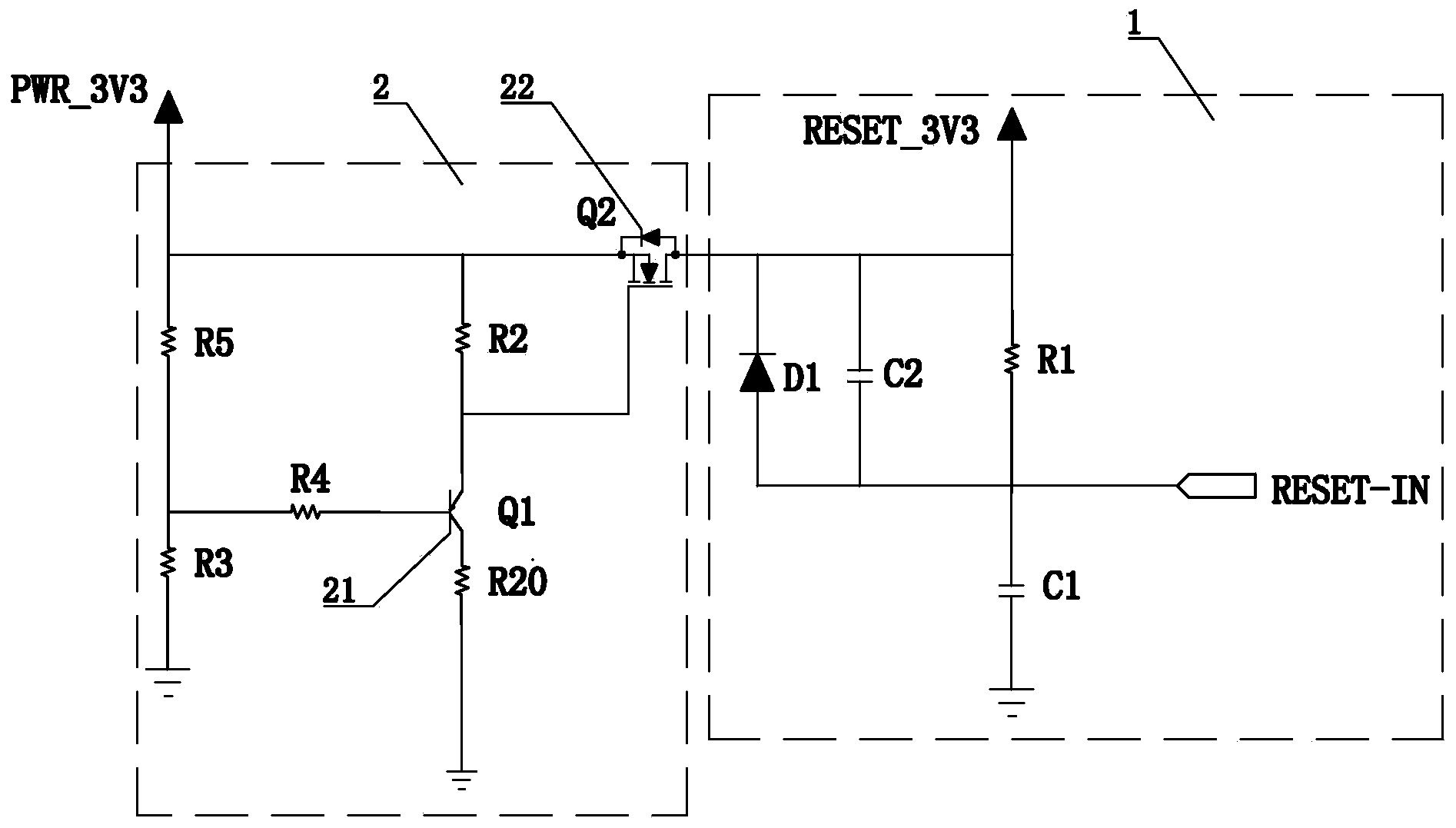
[0024] Such as figure 2 As shown, an RC reset circuit with a power supply detection and control function includes an RC circuit 1 and a power supply PWR_3V3. The RC circuit 1 includes a resistor R1, a capacitor C2, and a diode D1 connected in parallel, and one end of the parallel connection is connected to the reset power supply RESET_3V3, and the other One end is respectively connected to the capacitor C1 and the reset input terminal RESET_IN, the other end of the capacitor C1 is grounded, and a power supply inspection circuit 2 is connected between the RC circuit 1 and the power supply PWR_3V3. The power supply inspection circuit 2 is provided with a total input terminal and A total output terminal, the total input terminal is electrically connected to the power supply PWR_3V3, the total output terminal is electrically connected to the RC circuit 1, and the power supply detection and control circuit 2 is used to detect the voltage of the power supply PWR_3V3, and according t...

Embodiment 2

[0027]Embodiment 2 is basically the same as Embodiment 1, except that: the primary switch element 21 is a PNP transistor Q1, the emitter is a primary output terminal, and the collector is a primary input terminal; the secondary switch element 22 is an NMOS type transistor Q1. Effect tube Q2. The resistance value of the resistor R20 is 0, and the resistance value of the resistor R2 is greater than 0, which ensures that the PNP transistor Q1 and the NMOS field effect transistor Q2 are turned on or off according to the voltage of the power supply PWR_3V3.

[0028] The working process is: the triode Q1 is PNP (MMBT3906), it is turned on when the base voltage is less than 0.5V, and the field effect transistor Q2 is NMOS, and it is turned on when the gate voltage is greater than 0.5V. When the voltage of the power supply PWR_3V3 is less than 2.92V, it is calculated by the formula <2.92 / (R5+R3)*R3, the base voltage of the transistor Q1 is less than 0.5V, the transistor Q1 is in the c...

Embodiment 3

[0029] Embodiment 3: basically the same as Embodiment 1, the difference is that the emitter of the first-level element 21, the transistor Q1, is the first-level output end, the collector is the first-level input end, and the second-level switching element 22 is an NMOS type field effect transistor Q2, The gate of the field effect transistor Q2 is electrically connected to the emitter; the resistance value of the resistor R20 is greater than 0, and the resistance value of the resistor R2 is 0, so that the NPN transistor Q1 and the NMOS transistor Q2 are turned on or off according to the voltage of the power supply PWR_3V3 Cut off the power supply PWR_3V3.

[0030] The working process is as follows: the transistor Q1 is NPN (MMBT3904), it is turned on when the base voltage is greater than 0.5V, and the field effect transistor Q2 is NMOS, and it is turned on when the gate voltage is greater than 0.5V. When the voltage of the power supply PWR_3V3 is less than 2.92V, calculated by ...


PUM

PropertyMeasurementUnit
Resistanceaaaaaaaaaa

Abstract

The invention discloses an RC reset circuit with a power supply inspection and control function. The RC reset circuit comprises an RC circuit and a power supply. A power supply inspection and control circuit is connected between the RC circuit and the power supply and is provided with a total input end and a total output end. The total input end is electrically connected with the power supply. The total output end is electrically connected with the reset power supply of the RC circuit. The power supply inspection and control circuit is used for detecting the voltage of the power supply and turns on and turns off the power supply according to the voltage. When the power supply voltage is not stable and the state of a system peripheral circuit with the needed of reset is not stable, the power supply and the RC circuit are disconnected by the power supply inspection and control circuit, a reset input end RESET_IN potential is low, and the system with the need of reset is not reset and started. When the power supply voltage is stable and the state of the system peripheral circuit with the needed of reset is stable, the power supply and the RC circuit are connected by the power supply inspection and control circuit, a reset input end RESET_IN potential is high, and the system with the need of reset is reset and started. Thus the condition that the system is not disordered in reset is ensured, and the working is not influenced.

Description

technical field [0001] The invention relates to the technical field of RC reset circuits, in particular to an RC reset circuit with a power supply detection and control function. Background technique [0002] In the prior art, the RC reset circuit such as figure 1 As shown, it includes an RC circuit and a reset power supply RESET_3V3. The RC circuit includes a resistor R1, a capacitor C2, and a diode D1 connected in parallel. One end of the three components connected in parallel is connected to the power supply PWR_3V3, and the other end is connected to the capacitor C1 and the reset input terminal RESET_IN respectively. The other end of the capacitor C1 is grounded. The existing RC reset circuit mainly uses the power supply PWR_3V3 to directly charge through the RC circuit to realize the delayed reset of the system that needs to be reset. Since the existing RC reset circuit does not have the function of detecting and controlling the power supply voltage, when the power su...

Claims


Application Information

Patent Timeline
IPC IPC(8): H03K17/22
Inventor 曾利民
Owner QINGDAO GOERTEK
Learn More