Ultrasonic transducer device, probe, electronic instrument, and ultrasonic diagnostic device

A transducer and ultrasonic technology, applied in ultrasonic/sonic/infrasonic diagnosis, sonic diagnosis, infrasonic diagnosis, etc., can solve the problems of reduced sensitivity, inability to detect the sensitivity of piezoelectric elements, and reduced

Active Publication Date: 2014-03-26
SEIKO EPSON CORP
View PDF11 Cites 20 Cited by
  • Summary
  • Abstract
  • Description
  • Claims
  • Application Information

AI Technical Summary

Problems solved by technology

A reduction in polarization leads to a reduction in sensitivity, which in turn leads to a deterioration in the accuracy of the assay
However, the sensitivity of the piezoelectric element cannot be checked without using other devices such as calibration devices other than the ultrasonic transducer device

Method used


Image

  • Ultrasonic transducer device, probe, electronic instrument, and ultrasonic diagnostic device
  • Ultrasonic transducer device, probe, electronic instrument, and ultrasonic diagnostic device
  • Ultrasonic transducer device, probe, electronic instrument, and ultrasonic diagnostic device

Examples


Embodiment Construction

[0051] Hereinafter, one embodiment of the present invention will be described with reference to the drawings. In addition, the present embodiment described below does not unreasonably limit the content of the present invention described in the claims, and all the structures described in the present embodiment are not essential as the solution means of the present invention.

[0052] (1) The overall structure of the ultrasonic diagnostic device

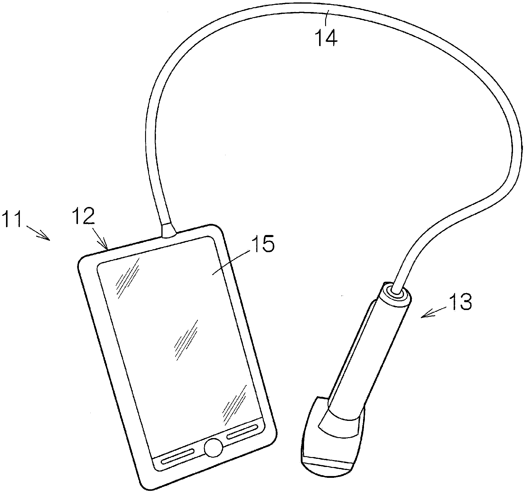
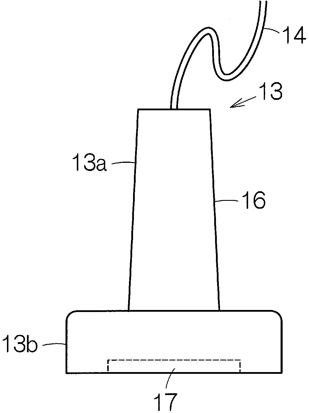
[0053] figure 1 A configuration of an ultrasonic diagnostic apparatus 11 , which is a specific example of electronic equipment according to an embodiment of the present invention, is schematically shown. The ultrasonic diagnostic apparatus 11 includes an apparatus terminal 12 and an ultrasonic probe (probe) 13 . The device terminal 12 and the ultrasonic probe 13 are connected to each other by a cable 14 . The device terminal 12 and the ultrasonic probe 13 exchange electric signals through the cable 14 . A display panel (display dev...


PUM


Abstract

The invention relates to an ultrasonic transducer device, a probe, an electronic instrument, and an ultrasonic diagnostic device. The ultrasonic transducer device is characterized by comprising a substrate, a vibrating film, a piezoelectric element, an input section and a detection section. The substrate has a plurality of openings. The vibrating film provided in each of the openings to cover a corresponding one of the openings. The piezoelectric element is provided in each of the openings on the vibrating film. The input section is configured and arranged to input a drive signal to a part of piezoelectric elements among the piezoelectric elements. The detection section is configured and arranged to detect vibration of the piezoelectric elements, in which the drive signal is not inputted, among the piezoelectric elements while the drive signal is inputted to the part of the piezoelectric elements among the piezoelectric elements.

Description

technical field [0001] The present invention relates to an ultrasonic transducer device, a probe using the same, electronic equipment, an ultrasonic diagnostic device, and the like. Background technique [0002] The ultrasonic transducer device may have one substrate. An opening is formed on the substrate. Ultrasonic transducer elements are provided in the respective openings. The ultrasonic transducer element has a vibrating membrane. The diaphragm closes the opening from the surface of the substrate. A piezoelectric element is mounted on the vibrating membrane. Vibration of the diaphragm is induced for each ultrasonic transducer element under the action of the piezoelectric element. Ultrasonic waves are generated with the vibration of the diaphragm. In this ultrasonic transducer device, the piezoelectric film of the piezoelectric element can be formed thinly. [0003] As disclosed in Patent Document 1, the piezoelectric film is surely polarized. If the piezoelectri...

Claims


Application Information

Patent Timeline
Patent Type & Authority Applications(China)
IPC IPC(8): A61B8/00B06B1/06
CPCB06B2201/76B06B1/0215A61B8/4483B06B1/0629A61B8/4494
Inventor 西胁学
Owner SEIKO EPSON CORP
Why Eureka
Try Eureka