Prefilling injector

A technology of prefilled syringes and cartridges, applied in the field of mechanical connection structures, can solve the problems of unfavorable popularization, lower costs, and higher thresholds for use

Active Publication Date: 2014-03-26
BERPU MEDICAL TECH CO LTD
View PDF10 Cites 10 Cited by
  • Summary
  • Abstract
  • Description
  • Claims
  • Application Information

AI Technical Summary

Problems solved by technology

[0005] Existing pre-filled syringes, catheter flushers, and pre-flushed syringes need to be re-established for special production lines

Method used


Image

  • Prefilling injector
  • Prefilling injector
  • Prefilling injector

Examples


Embodiment Construction

[0039] The present invention will be further described below with reference to the accompanying drawings.

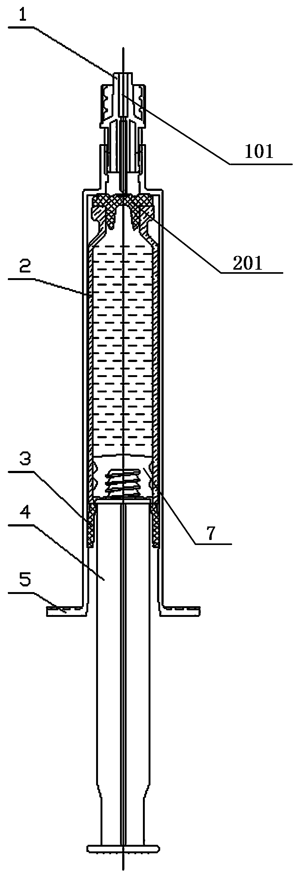
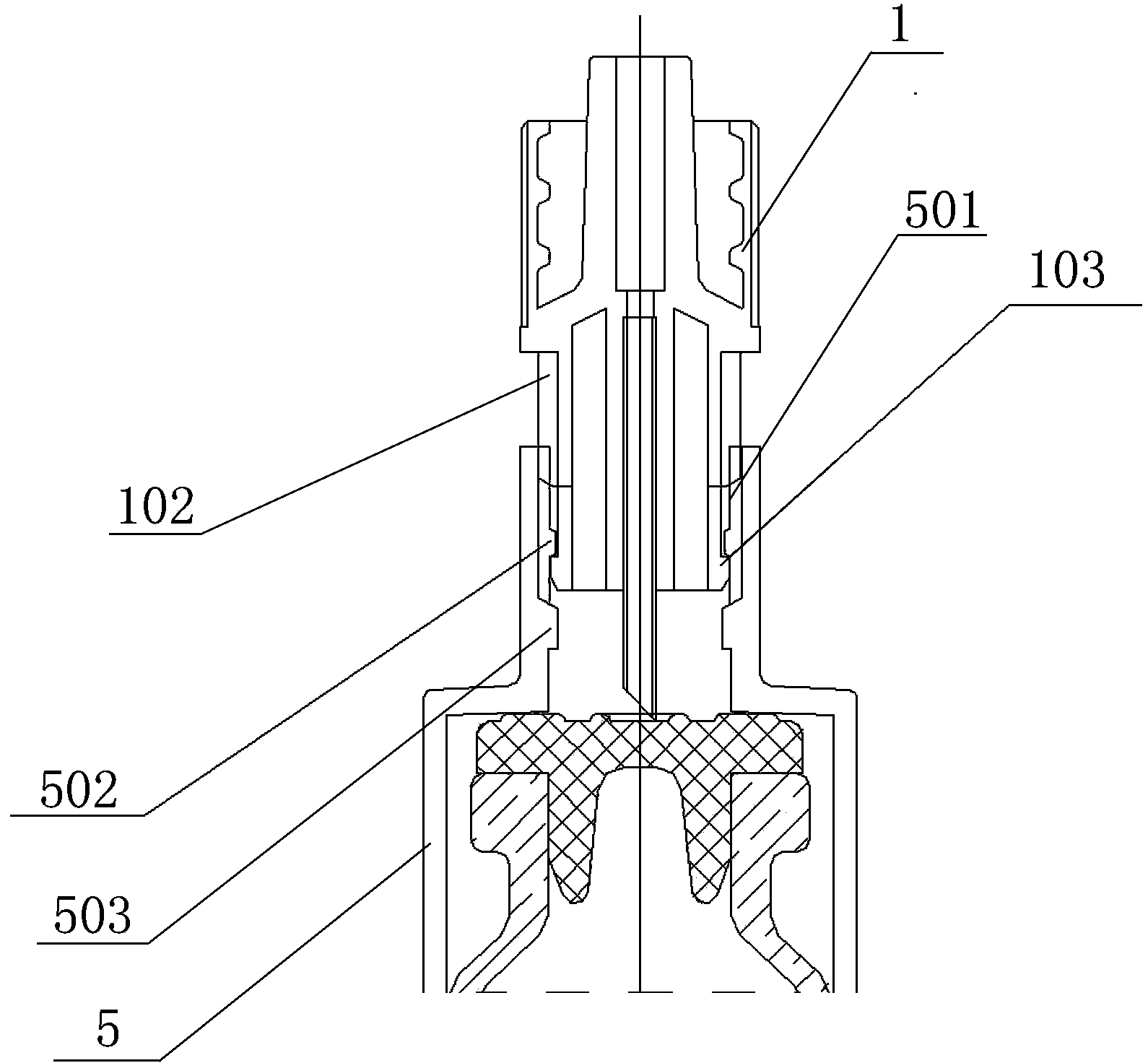
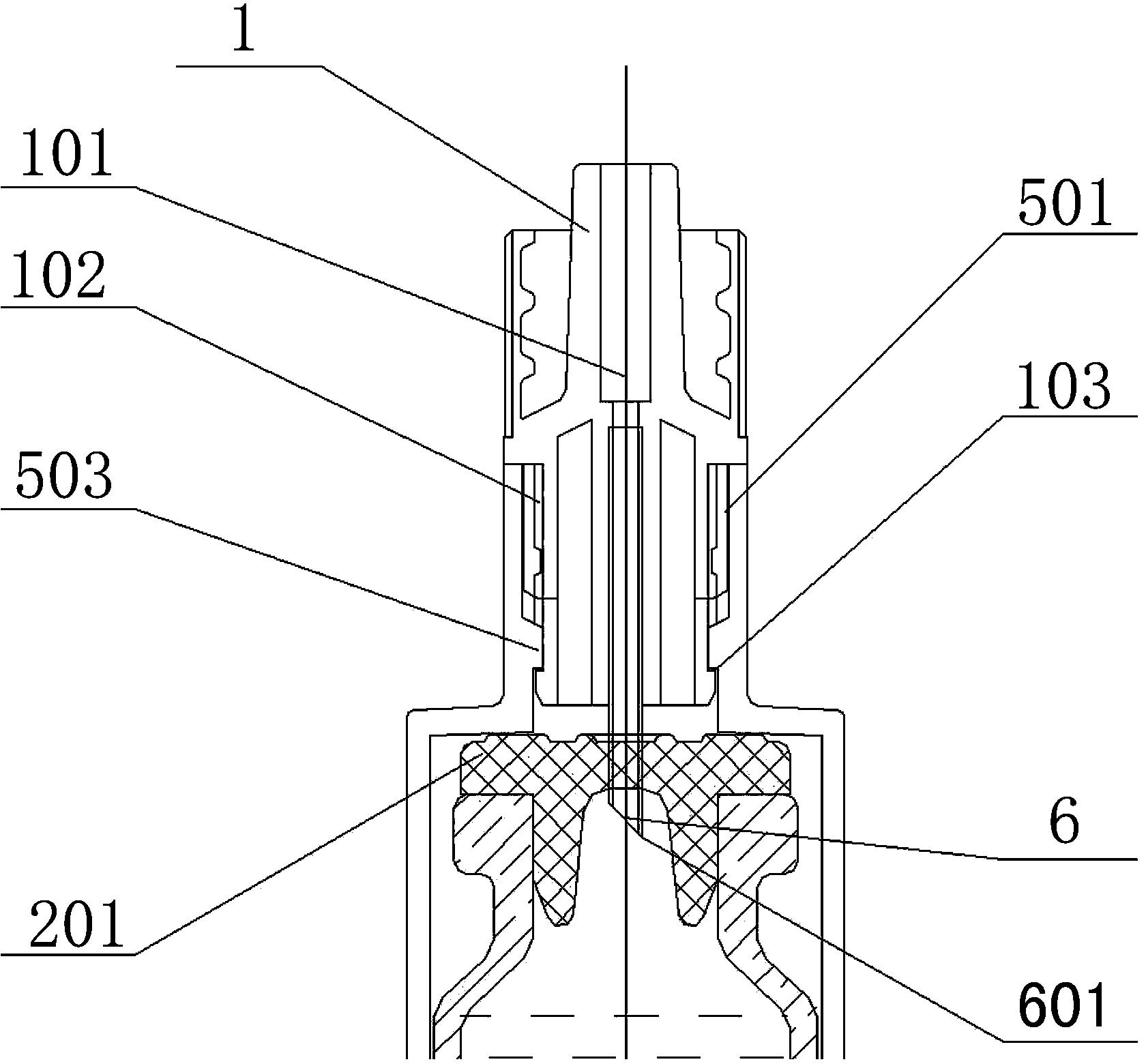
[0040] The present invention is a prefilled syringe. In the first embodiment of the patent of the present invention, it includes an outer sleeve 5, which is different from the prior art in that: the outer sleeve 5 is provided with a cartridge bottle 2, and the outer sleeve 5 The neck of the upper end is provided with a spiral seat 1, and the lower part of the spiral seat 1 is provided with a puncture needle 6. It protrudes from the lower part of the spiral seat 1 and is located in the neck of the outer sleeve 5. The free end of the puncture needle 6 forms a thorn point 601. The inner wall of the inner cavity of the outer sleeve 5 is provided with a fixed sleeve 3, and the upper end of the fixed sleeve 3 is against the clamping The lower end of the bottle 2, the rubber plug 7 at the upper end of the core rod 4 is located in the cavity near the lower end of the cartridge 2...


PUM


Abstract

The invention discloses a prefilling injector. The prefilling injector is characterized in that a design structure is that the front end of the injector has to be provided with at least one communicating seat, an injector barrel is internally provided with a clamping bottle, the communicating seats are separated from the clamping bottle in an initial state, and the communicating seats or the clamping bottle can be moved when in use to be communicated with the same to complete injection. The prefilling injector has the advantages that the injector can be additionally arranged on an existing liquid medicine bottle to complete the injection, while special production lines need to be rebuilt to produce other prefilling injectors, catheter flushers and prefilling flushing injectors, so that the threshold of widespread use can be greatly lowered.

Description

technical field [0001] The invention relates to the technical field of medical devices, in particular to a prefilled syringe, and particularly to its mechanical connection structure. Background technique [0002] Comparative document 1, patent number: CN201080065717.4, application date: 2010.12.28, application publication number: CN102821803A, patentee: Terumo Co., Ltd., this case discloses "a prefilled syringe", which consists of a prefilled The prefilled syringe body consists of an outer cylinder, a gasket accommodated in the outer cylinder so as to be slidable in the outer cylinder, and a seal for sealing the front end opening of the outer cylinder. A component, a drug that is stored in a drug storage portion formed in the outer cylinder, the plunger is attached to the gasket or can be attached to the gasket, and the gasket is characterized in that the front end of the gasket is closed and the rear end is open. It is a cylindrical body, and is composed of a gasket main b...

Claims


Application Information

Patent Timeline
IPC IPC(8): A61M5/24A61M5/31
Inventor 张林锋
Owner BERPU MEDICAL TECH CO LTD
Why Eureka
Try Eureka