Ventilator sychronization indicator

A respirator and indication technology, which is applied in the direction of respirator, evaluation of respiratory organs, sensors, etc., can solve problems such as difficulty in determining, difficulty in breathing of patients and performance of respirator

Active Publication Date: 2014-03-26
GENERAL ELECTRIC CO
View PDF7 Cites 7 Cited by
  • Summary
  • Abstract
  • Description
  • Claims
  • Application Information

AI Technical Summary

Problems solved by technology

Monitoring patient breathing and respirator performance can be difficult with existing respirators
It may not be easy for the caregiver to determine if the patien

Method used


Image

  • Ventilator sychronization indicator
  • Ventilator sychronization indicator
  • Ventilator sychronization indicator

Examples


Embodiment Construction

[0040] figure 1 One example of a mechanical ventilation system 10 is shown schematically. Ventilation system 10 provides a pneumatic circuit that brings breathing gas to patient 13 and exhaled air away from patient 13 in order to assist patient 13 to breathe. As will be described below, ventilation system 10 provides a graphic that allows caregivers to more quickly and easily monitor patient breathing and ventilator performance. The ventilation system 10 enables the caregiver to more easily determine whether the patient is struggling to breathe, whether the patient is resisting the assistance of the ventilator, or whether the ventilator is operating optimally to help the patient breathe. The ventilation system 10 includes a respirator 12 , a breathing circuit 14 , a sensor 16 and a display and control unit 18 .

[0041] The ventilator 12 provides gas, such as air or air containing anesthetics, medicines, etc., to the patient 13 through the breathing circuit 14 and receives e...


PUM


Abstract

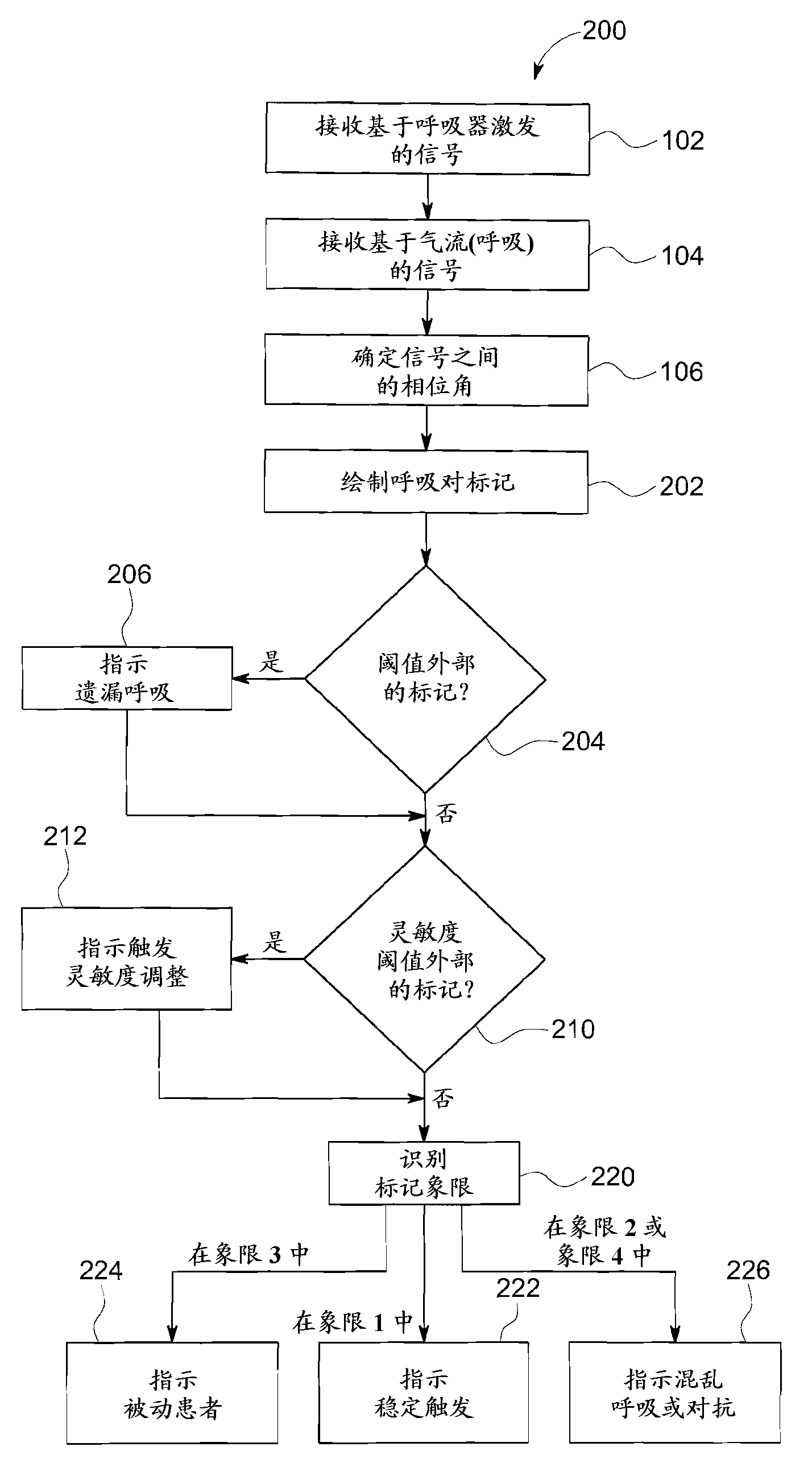
A method and apparatus determine a phase angle between a first signal based on ventilator airflow for a breath and a second signal based upon ventilator firing for the breath. Based on the phase angle, an indication of a nature of dis-synchrony of airflow and ventilator firing is provided.

Description

technical field [0001] The present invention relates to respirator synchronization indicators. Background technique [0002] A ventilator is a machine used to assist or replace a patient's spontaneous breathing. In some cases, ventilators are also used to deliver anesthesia to patients undergoing certain medical procedures. With existing respirators, monitoring patient breathing and respirator performance can be difficult. It may not be easy for a caregiver to determine if the patient is struggling to breathe, if the patient is resisting the assistance of the ventilator, or if the ventilator is operating optimally to help the patient breathe. Contents of the invention [0003] According to a first aspect of the present disclosure, there is provided an apparatus comprising: [0004] display; and [0005] a processing unit that receives a first input of airflow in a breath-based respirator and a second input of a firing of the breath-based respirator, wherein the process...

Claims


Application Information

Patent Timeline
IPC IPC(8): A61M16/00
CPCA61M16/12A61M16/0808A61B5/087A61B2562/0247A61M16/22A61M2205/3331A61M2016/0027A61M16/0866A61M2016/0015A61B5/08A61M2016/1025A61M16/16A61M2202/0208A61M2205/80A61M2016/0036A61M16/0051A61M2205/502A61M16/0833A61M16/024A61M2205/52
Inventor J.B.科滕
Owner GENERAL ELECTRIC CO
Why Eureka
Try Eureka