
Electromagnet mechanism type centrifugal machine door lock

An electromagnet and centrifuge technology, applied in the field of door locks, can solve problems such as personal injury and non-compliance with the safety operation requirements of the centrifuge, and achieve the effect of avoiding injury and ensuring safe operation.

Active Publication Date: 2014-03-26
ANHUI USTC ZONKIA SCI INSTR
View PDF5 Cites 3 Cited by
  • Summary
  • Abstract
  • Description
  • Claims
  • Application Information

AI Technical Summary

Problems solved by technology

During normal operation, the door lock can remain locked, but when the power is accidentally cut off, the electrical control system will immediately lose power and release the door lock holding mechanism, making it possible to open the door lock. At this time, the high-speed rotating parts in the centrifugal cavity may be damaged The above design does not meet the requirements for the safe operation of the centrifuge

Method used


Image

  • Electromagnet mechanism type centrifugal machine door lock

Examples


Embodiment 1

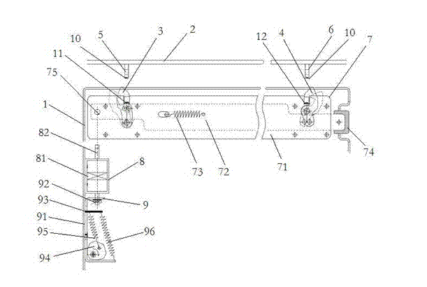
[0017] In order to improve the control degree of the automatic locking mechanism 7, a magnetic column 10 can be installed at the bottom of the left / right deadbolt 5,6, and a hook sensor 11, which is opposite to the magnetic column 10, is installed on the left / right hook 3,4. 12. The hook sensors 11 and 12 are connected with the control system signal of the centrifuge.

[0018] When the magnetic column 10 is close to the hook sensors 11, 12, the output of the hook sensors 11, 12 changes from high level to low level under the action of the magnetic field. When the machine detects that the hook sensors 11 and 12 all become low level, it shows that the door cover has been fully closed now.

Embodiment 2

[0020] In order to ensure that the door cover 2 can be safely opened after an accidental power failure during centrifugal operation, the technical solution of this embodiment is to provide a manual toggle hole on the eccentric wheel 94 .

[0021] Accidental power failure during centrifugal work, iron core 82 positions remain unchanged, elastic push plate 72 still can not promote, and door cover 2 keeps locking. Only after the centrifuge stops running completely, use a special tool to rotate the eccentric wheel through the manual toggle hole, so that the movable bracket 91 drives the iron core 82 to move in the opposite direction, and the head of the iron core 82 withdraws from the limit hole 75, then the door cover 2 can be moved. Safe open.


PUM


Abstract

The invention discloses an electromagnet mechanism type centrifugal machine door lock which comprises a machine body and a door cover. The top of the machine body is provided with left and right hooks; the bottom of the door cover is provided with left and right bolts which are in fit with the left and right hooks; an automatic lock catch mechanism capable of automatically inserting the hooks into the bolts is arranged in the machine body; the automatic lock catch mechanism comprises a Z-shaped elastic push plate; the elastic push plate is formed by additionally arranging a spring on a push plate body; horizontal pushing on the elastic push plate is implemented by pressing a hidden sleeve which is arranged at one end of the push plate body and extends out of the machine body; resetting is implemented by utilizing the spring; the other end of the elastic push plate is provided with a limiting hole; the lateral surface of the elastic push plate is provided with an electromagnet mechanism; the electromagnet mechanism comprises a bidirectional electromagnet; the bidirectional electromagnet is provided with an iron core capable of being inserted into the limiting hole; and the lower part of the bidirectional electromagnet is fixed in a telescopic elastic mechanism. According to the invention, the door lock can be kept in a locked state under the conditions that a centrifugal machine normally operates and is powered off by accident, so that operation safety of personnel is ensured.

Description

technical field [0001] The invention relates to a door lock, in particular to a door lock device for the safety protection of a centrifuge. Background technique [0002] In the prior art, most centrifuge door locking mechanisms utilize mechanical structure and electrical control to achieve locking. During normal operation, the door lock can remain locked, but when the power is accidentally cut off, the electrical control system will immediately lose power and release the door lock holding mechanism, making it possible to open the door lock. At this time, the high-speed rotating parts in the centrifugal cavity may be damaged The above design does not meet the requirements for the safe operation of the centrifuge. Contents of the invention [0003] The object of the present invention is to overcome the shortcomings of the above-mentioned prior art, and provide a safe, effective, simple in structure and convenient to use electromagnet mechanism type centrifuge door lock. ...

Claims


Application Information

Patent Timeline
IPC IPC(8): B04B7/00E05B65/00E05B47/06
Inventor 田杰唐俊标陈炯操和江张献明吴立佳林振兴崔杰张满
Owner ANHUI USTC ZONKIA SCI INSTR
Learn More