
Correction device

A technology of deviation correction device and bearing seat, which is applied in the field of deviation correction device, and achieves the effects of wide application range, high usability and versatility, and simple maintenance

Active Publication Date: 2015-09-30
CHANGZHOU BAOLING HEAVY IND MACHINERY
View PDF8 Cites 0 Cited by
  • Summary
  • Abstract
  • Description
  • Claims
  • Application Information

AI Technical Summary

Problems solved by technology

The traditional method has strict requirements on the shape of the incoming steel plate. If the cross-sectional size of the strip changes greatly in the length and width directions, the traditional deviation correction method cannot correct the deviation of the strip steel to meet the requirements of the rolling mill.

Method used


Image

  • Correction device

Examples


Embodiment Construction

[0018] The present invention will be further described below in conjunction with the accompanying drawings:

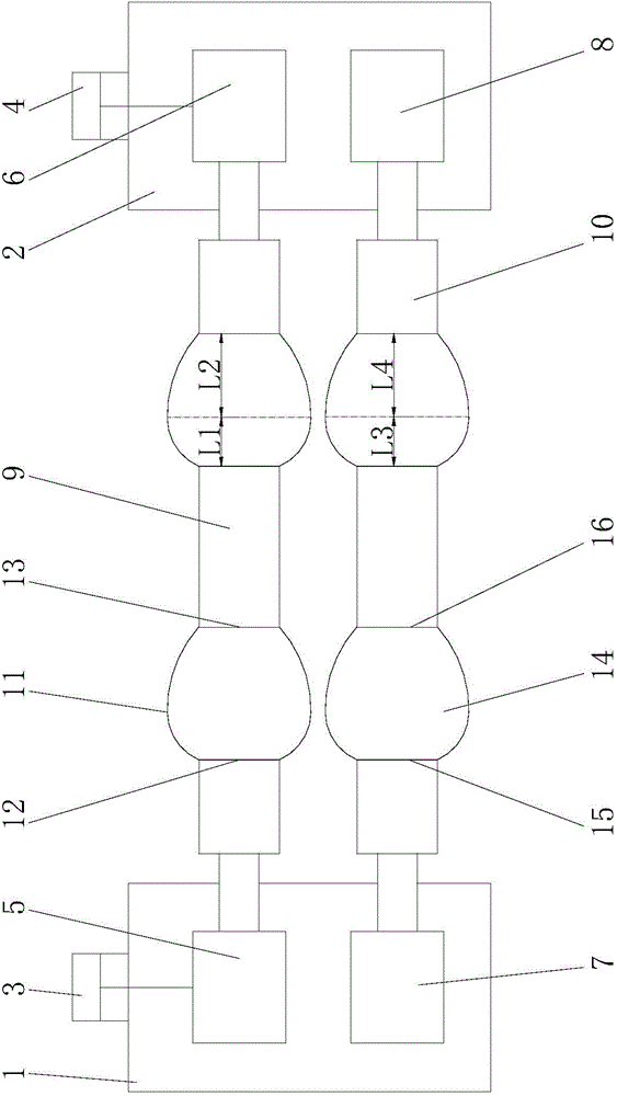
[0019] refer to figure 1 , The deviation correction device of the present invention includes a first frame 1, a second frame 2, a driving side hydraulic cylinder 3, an operating side hydraulic cylinder 4, a first bearing seat 5, a second bearing seat 6, a third bearing seat 7, a fourth Bearing housing 8 , upper work roll 9 and lower work roll 10 .

[0020] The driving side hydraulic cylinder 3 is fixed on the upper part of the first frame 1 , and the piston rod of the driving side hydraulic cylinder 3 extends along the longitudinal direction of the first frame 1 and is connected to the first bearing seat 5 . The operation side hydraulic cylinder 4 is fixed on the upper part of the second frame 2 , and the piston rod of the operation side hydraulic pressure 4 extends along the longitudinal direction of the second frame 2 and is connected to the second bearing seat 6 . ...


PUM


Abstract

The invention relates to a deviation rectification device. A piston rod of a driving side hydraulic cylinder extends in the longitudinal direction of a first frame, and then is connected with a first bearing block, a piston rod of an operating side hydraulic cylinder extends in the longitudinal direction of a second frame, and then is connected with a second bearing block, one end of an upper working roll is connected with the first bearing block, the other end of the upper working roll is connected with the second bearing block, at least two first annular protrusions are arranged on the circumferential surface of the upper working roll, the surface of each first annular protrusion is an arc-shaped surface, a third bearing block is fixed to the first frame, and is arranged below the first bearing block, a fourth bearing block is fixed to the second frame, and is arranged below the second bearing block, one end of a lower working roll is connected with the third bearing block, the other end of the lower working roll is connected with the fourth bearing block, at least two second annular protrusions are arranged on the circumferential surface of the lower working roll, and the surface of each second annular protrusion is an arc-shaped surface. The deviation rectification device achieves deviation rectification on the situation that the dimensions of fed steel plates are not strictly required.

Description

technical field [0001] The invention relates to the technical field of strip steel hot rolling production lines, in particular to a deviation correction device. Background technique [0002] In recent years, with the rapid development of hot rolling technology, the rolling speed has been continuously increased, and the production capacity requirements of the rolling line have become higher and higher. technology. In the hot rolling production line or the new thin strip continuous casting and rolling production line, the shape of the thin strip steel plate is poor, and the cross-sectional dimensions in the two directions of length and width are inconsistent, often irregular, and the thin strip steel needs to be corrected before entering the rolling mill. Real-time deviation correction ensures that the strip enters the rolling mill smoothly for normal rolling. [0003] For users, they do not want a very complicated rectification device, so they require a rectification device...

Claims


Application Information

Patent Timeline
Patent Type & Authority Patents(China)
IPC IPC(8): B21B39/14
Inventor 董春光
Owner CHANGZHOU BAOLING HEAVY IND MACHINERY
Learn More