
Large combined dual-jacking mould structure

A combined, ejector mechanism technology, applied in the direction of manufacturing tools, forging/pressing/hammer devices, forging/pressing/hammering machinery, etc., can solve the problem that the upper mold cannot be demoulded, etc., to reduce processing costs and reduce processing costs. Repair cost, weight and size reduction effects

Inactive Publication Date: 2014-03-26
WUXI TURBINE BLADE
View PDF5 Cites 8 Cited by
  • Summary
  • Abstract
  • Description
  • Claims
  • Application Information

AI Technical Summary

Problems solved by technology

[0003] In view of the above problems, the present invention provides a large-scale combined double ejector die structure, which can solve the problem that the upper die cannot be demoulded when the large deep cavity thin-walled forging is forged with the existing single lower ejector die. Convenient, both the upper and lower dies can realize the ejection and demoulding of forgings

Method used


Image

  • Large combined dual-jacking mould structure

Examples


Embodiment Construction

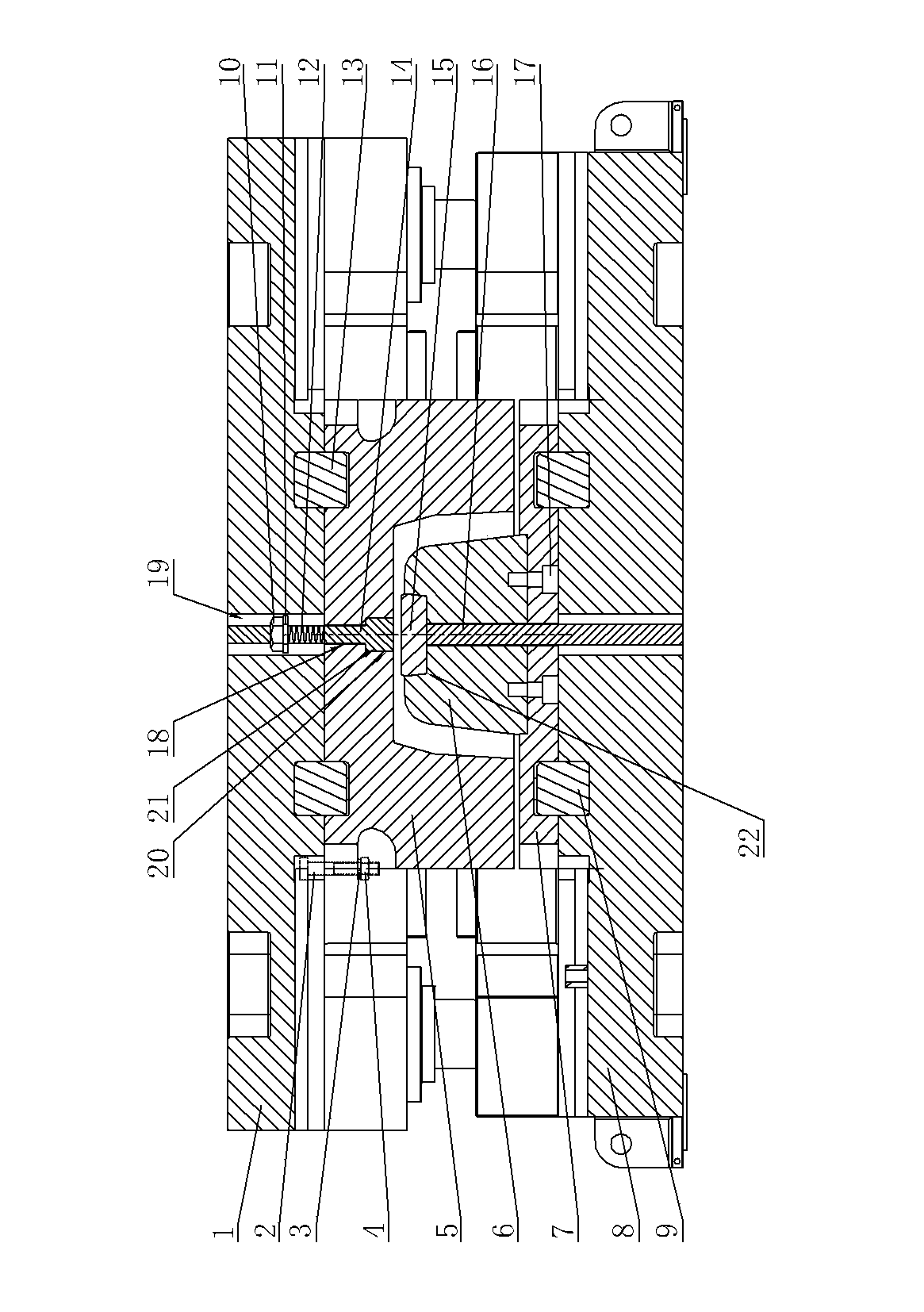
[0019] See figure 1 , the mold of the present invention comprises an upper mold structure and a lower mold structure, the upper mold structure includes an upper mold base 1 and an upper mold 5, the upper mold 5 is installed under the upper mold base 1, and a lower mold ejection mechanism is installed in the lower mold structure, the upper mold The upper mold ejection mechanism is installed in the mold structure. The upper mold ejection mechanism includes an upper ejector rod 14 and a compression spring 12. The upper ejector rod 14 passes through the upper mold 5 and the upper ejector rod of the upper mold base 1 from bottom to top in sequence. Holes 18, 19, the bottom flange 20 of the upper die 14 and the groove 21 of the upper mold 5 are clearance fit, and the aperture of the upper ejector mounting hole 19 of the upper die base 1 is larger than that of the upper ejector mounting hole 18 of the upper die 5 Aperture, the upper ejector rod 14 is located in the part of the outer ...


PUM


Abstract

The invention provides a large combined dual-jacking mould structure. The large combined dual-jacking mould structure can solve the problem that an upper mould cannot perform demoulding when an existing single-jacking mould is used for forging a large deep-cavity thin-walled forge piece. The large combined dual-jacking mould structure is simple and convenient to process and assemble; and the upper mould and a lower mould can both achieve demoulding of the forge piece in a jacking mode. The large combined dual-jacking mould structure comprises an upper mould structure and a lower mould structure; the upper mould structure comprises an upper mould base and the upper mould, wherein the upper mould is mounted beneath the upper mould base; a lower mould jacking mechanism is mounted in the lower mould structure. The large combined dual-jacking mould structure is characterized in that an upper mould jacking mechanism is mounted in the upper mould structure; the upper mould jacking mechanism comprises an upper jacking rod and a compression spring; the upper jacking rod sequentially penetrates through the upper mould and an upper jacking rod mounting hole of the upper mould base from bottom to top; the flange at the bottom of the upper jacking rod is in clearance fit with a groove of the upper mould; the diameter of the upper jacking rod mounting hole of the upper mould base is larger than that of an upper jacking rod mounting hole of the upper mould; the part, located in the upper jacking rod mounting hole of the upper mould base, of the upper jacking rod is sleeved with the compression spring which is locked on the top surface of the upper mould through a tight nut and a flat washer.

Description

technical field [0001] The invention relates to the field of forming and forging die structures, in particular to a large-scale combined double-ejection die structure. Background technique [0002] For forgings that are generally difficult to eject, most of the molds use a single lower ejector die, that is, there is only one lower ejector mechanism in the mold, and the forging can only be ejected upward by the lower ejector mechanism to demould the forging, but for some For special forgings such as large deep-cavity thin-walled forgings, the forgings will not be able to exit the lower die due to the high cavity, and will easily hug the punch due to cooling shrinkage and cannot exit the upper die. Therefore, if only the lower ejection die is used for this type of forging, the forging is prone to die-holding, resulting in production interruption or the scrapping of the forging and the die. , resulting in serious material waste and low material utilization rate; in addition, b...

Claims


Application Information

Patent Timeline
Patent Type & Authority Applications(China)
IPC IPC(8): B21J13/14B21J13/02
Inventor 周俊赵顺峰吴德振
Owner WUXI TURBINE BLADE
Learn More