Target assembly welding method

A welding method and target technology, applied in welding equipment, auxiliary devices, manufacturing tools, etc., can solve the problems of inability to meet long-term stable production and use of targets, short service life of target components, low sputtering uniformity of targets, etc. problems, to meet the long-term stable production and use of targets, improve the welding bonding rate, and achieve the effect of firm bonding

Active Publication Date: 2016-03-16
KONFOONG MATERIALS INTERNATIONAL CO LTD
View PDF11 Cites 0 Cited by
  • Summary
  • Abstract
  • Description
  • Claims
  • Application Information

AI Technical Summary

Problems solved by technology

[0007] The technical problem solved by the present invention is that due to the large deformation of the target in the target assembly, the sputtering uniformity of the target is low, and the service life of the target assembly is short, which cannot meet the long-term stable production and use of the target. needs

Method used


Image

  • Target assembly welding method
  • Target assembly welding method
  • Target assembly welding method

Examples


Embodiment Construction

[0047] The inventor found through serious research and analysis that the reasons for the above-mentioned technical problems are:

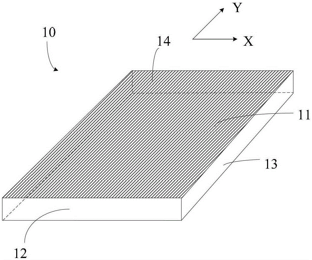
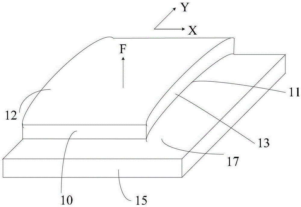
[0048] refer to figure 1 , the shape of the target 10 is a cuboid, and the target 10 includes a surface to be welded 11 , a sputtering surface 12 opposite to the surface to be welded 11 , and a side surface 13 between the surface to be welded 11 and the sputtering surface 12 . The surface 11 to be welded has processing lines 14 along the length direction (Y direction) of the target 10 . combined reference figure 1 and figure 2 , where, for a better understanding of the present invention, figure 2 The shortcomings of existing welding methods for target assemblies are exaggerated. The back plate 15 is placed on the welding platform, and the target material 10 is placed on the surface to be welded 17 of the back plate 15. At this time, the sputtering surface 12 of the target material 10 faces upward. When the target material 10 and the back plat...


PUM

PropertyMeasurementUnit
diameteraaaaaaaaaa

Abstract

A target module welding method comprises the steps of providing a target and a backing plate, enabling a to-be-welded surface of the target to be provided with a first processing line, and enabling the backing plate to be provided with a groove for accommodating the target; removing the first processing line, forming a second processing line on the to-be-welded surface, and enabling the length of the second processing line to be smaller than that of the first processing line; forming a first brazing filler metal layer on the to-be-welded surface of the target after the second processing line is formed; forming a second brazing filler metal layer on the bottom surface of the groove of the backing plate; placing the target in the groove, utilizing a welding process to weld the first brazing filler metal layer and the second brazing filler metal layer, and forming a target module. Deformation of the target in the target module can be reduced through the target module welding method, and sputtering uniformity of the target in the formed target module is improved and the service life of the target module is prolonged so as to meet the long-term stable production and target use requirements.

Description

technical field [0001] The invention relates to the field of semiconductor manufacturing, in particular to a method for reducing deformation of a target during welding. Background technique [0002] Vacuum sputtering is a process in which electrons accelerate to the substrate under the action of an electric field and collide with argon atoms, ionizing a large number of argon ions and electrons, and the electrons fly to the substrate, and the argon ions accelerate bombardment sputtering under the action of an electric field Sputtering a large number of target atoms, the neutral target atoms (or molecules) are deposited on the substrate to form a film, and finally achieve the purpose of coating the surface of the substrate. [0003] In the semiconductor industry, the target assembly is composed of a target that meets the sputtering performance and a back plate with a certain strength. The back plate can play a supporting role when the target assembly is assembled to the sputt...

Claims


Application Information

Patent Timeline
Patent Type & Authority Patents(China)
IPC IPC(8): B23K1/00B23K1/20
CPCB23K1/00B23K1/20B23K3/087
Inventor 姚力军相原俊夫大岩一彦潘杰王学泽方敏
Owner KONFOONG MATERIALS INTERNATIONAL CO LTD
Why Eureka
Try Eureka