Eureka AIR delivers breakthrough ideas for toughest innovation challenges, trusted by R&D personnel around the world.

Method for welding non-coating stainless steel plate in laser mode

A stainless steel plate and laser welding technology, applied in laser welding equipment, welding equipment, welding/welding/cutting items, etc., can solve the problems of large welding deformation of the outer surface of the wallboard, affecting the appearance effect, and showing oxidized color, etc., to achieve The effect of reducing the welding line, welding deformation is not scratched, and welding deformation is small

Active Publication Date: 2014-03-26
CRRC QINGDAO SIFANG CO LTD
View PDF5 Cites 6 Cited by
  • Summary
  • Abstract
  • Description
  • Claims
  • Application Information

AI Technical Summary

Problems solved by technology

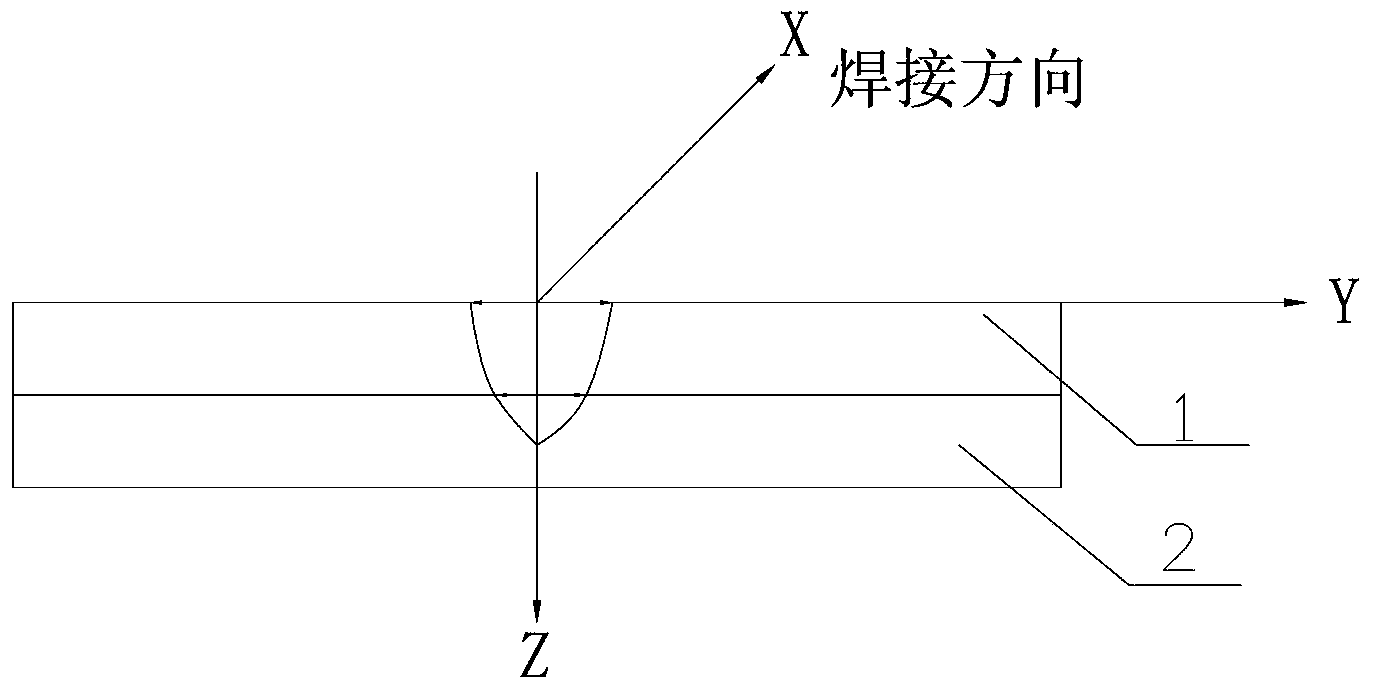
like figure 1 As shown, it is a schematic diagram of the traditional welding method. Although the traditional laser welding process can ensure the connection strength of the joint and the welding speed is fast, after welding, the outer surface of the wall panel will be deformed greatly, and at the same time, it will be damaged due to high temperature. The phenomenon of oxidation color appears. For the stainless steel car body with no coating process on the outer surface, its exposed surface has high requirements for commercialization. The deformation and discoloration caused by welding will directly affect its appearance

Method used


Image

  • Method for welding non-coating stainless steel plate in laser mode
  • Method for welding non-coating stainless steel plate in laser mode

Examples


Embodiment Construction

[0021] Below in conjunction with accompanying drawing and specific embodiment the present invention is described in further detail:

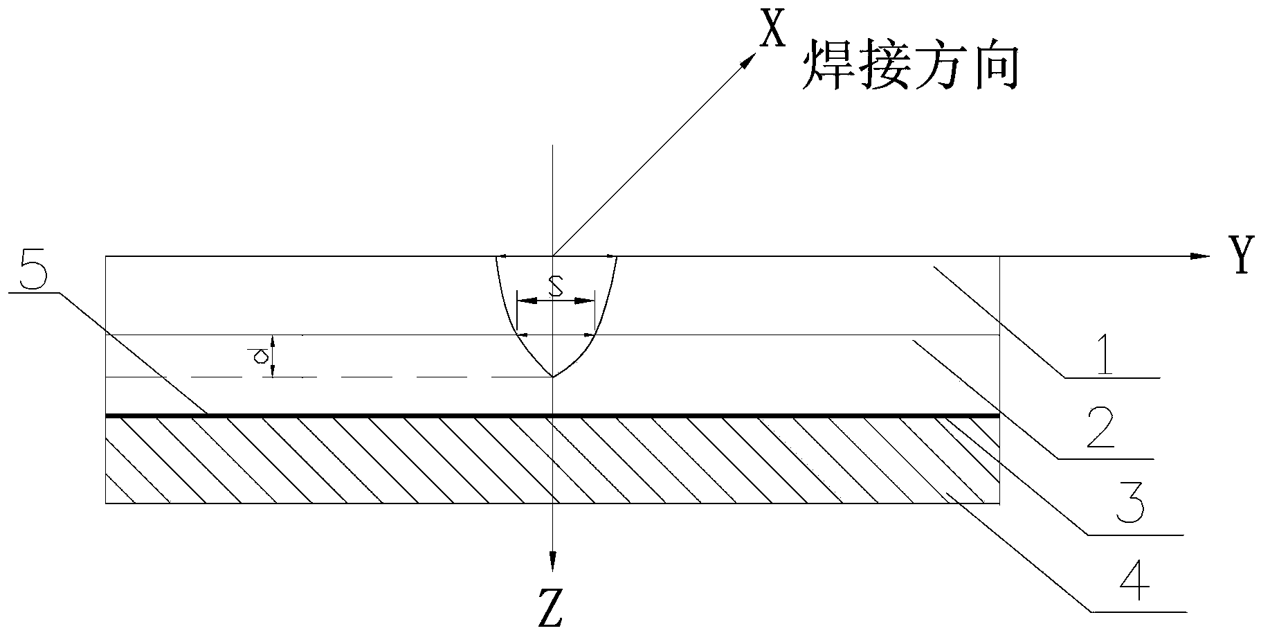
[0022] Such as figure 2 As shown, the laser welding method of a non-painted stainless steel plate according to the present invention is used for the welding connection between the outer wall panels of the stainless steel car body and the reinforcement members of the outer wall panels. Among them, the upper plate 1 refers to the reinforcement components on the exterior wall panels, such as support beams, etc., the lower plate 2 refers to the stainless steel exterior wall panels, and the back of the exterior wall panels is the outer surface 5 that needs to be exposed, and the outer surface 5 is not painted. , so the back of the exterior wall panels needs to meet higher requirements for commercial appearance, and the upper panel 1 is lapped on the front of the lower panel 2 for welding connection.

[0023] Before welding, a layer of protective fi...


PUM

PropertyMeasurementUnit
Thicknessaaaaaaaaaa
Thicknessaaaaaaaaaa
Thicknessaaaaaaaaaa

Abstract

The invention relates to a method for welding a non-coating stainless steel plate in a laser mode. An upper layer panel and a lower layer panel are stacked up, a layer of protecting film is arranged on the exposed surface of the lower layer panel, and the upper layer panel and the lower layer panel are connected by enabling a laser welding light beam to penetrate through the protecting film to reach a certain depth of the lower layer panel. On the premise that the assembling precision meets the laser welding requirements, the welding technology methods are selected in the aspects of controlling the appearance quality and guaranteeing the connector connecting strength according to the product requirements for a railway vehicle non-coating stainless steel vehicle body and the technology characteristics, and a certain welding width and a certain welding depth are controlled by controlling the welding technology parameters such as welding power and welding speed. The welding joint cannot be oxidized and the welding heat can be more centralized by adopting the special technologies of welding the exposed wall plate provided with the protecting film and placing an aluminum alloy base plate on the lower surface of a workpiece, the strength of the welding joint is guaranteed, the back face of the exposed welding joint cannot deform obviously, and the color of the back face of the exposed welding joint cannot change obviously.

Description

technical field [0001] The invention relates to a laser welding method for a stainless steel plate, in particular to a laser welding method for a stainless steel plate which requires the commercialization of an exposed surface. Background technique [0002] In rail vehicles such as subways, light rails, and EMUs, stainless steel car bodies have been gradually promoted and applied. Stainless steel materials have high strength and corrosion resistance, and are light in weight, low in maintenance costs, beautiful in appearance, and do not need to be painted on the outer surface. Features such as outfitting. In the prior art, a laser welding process is used for the welding between the stainless steel wallboard and the wallboard reinforcing member. Such as figure 1 As shown, it is a schematic diagram of the traditional welding method. Although the traditional laser welding process can ensure the connection strength of the joint and the welding speed is fast, after welding, the ...

Claims


Application Information

Patent Timeline
IPC IPC(8): B23K26/18B23K26/21B23K26/32
CPCB23K26/18B23K26/24B23K26/32B23K2101/006B23K2101/185B23K2103/50
Inventor 韩晓辉王素环刘胜龙
Owner CRRC QINGDAO SIFANG CO LTD
Why Eureka
Eureka Blog
Learn More