Automatic screw locking device based on computer vision

A computer vision and automatic lock technology, applied in the electrical field, can solve problems such as manufacturing precision deviation, locking failure, etc., and achieve the effect of independent control lines, tight coordination, and easy inspection of faults

Inactive Publication Date: 2014-03-26
YANFENG VISTEON AUTOMOTIVE ELECTRONICS
View PDF5 Cites 21 Cited by
  • Summary
  • Abstract
  • Description
  • Claims
  • Application Information

AI Technical Summary

Problems solved by technology

[0003] The object of the present invention is to provide an automatic locking screw device based on computer vision. The automatic locking screw device based on computer vision sh

Method used


Image

  • Automatic screw locking device based on computer vision

Examples


Embodiment 1

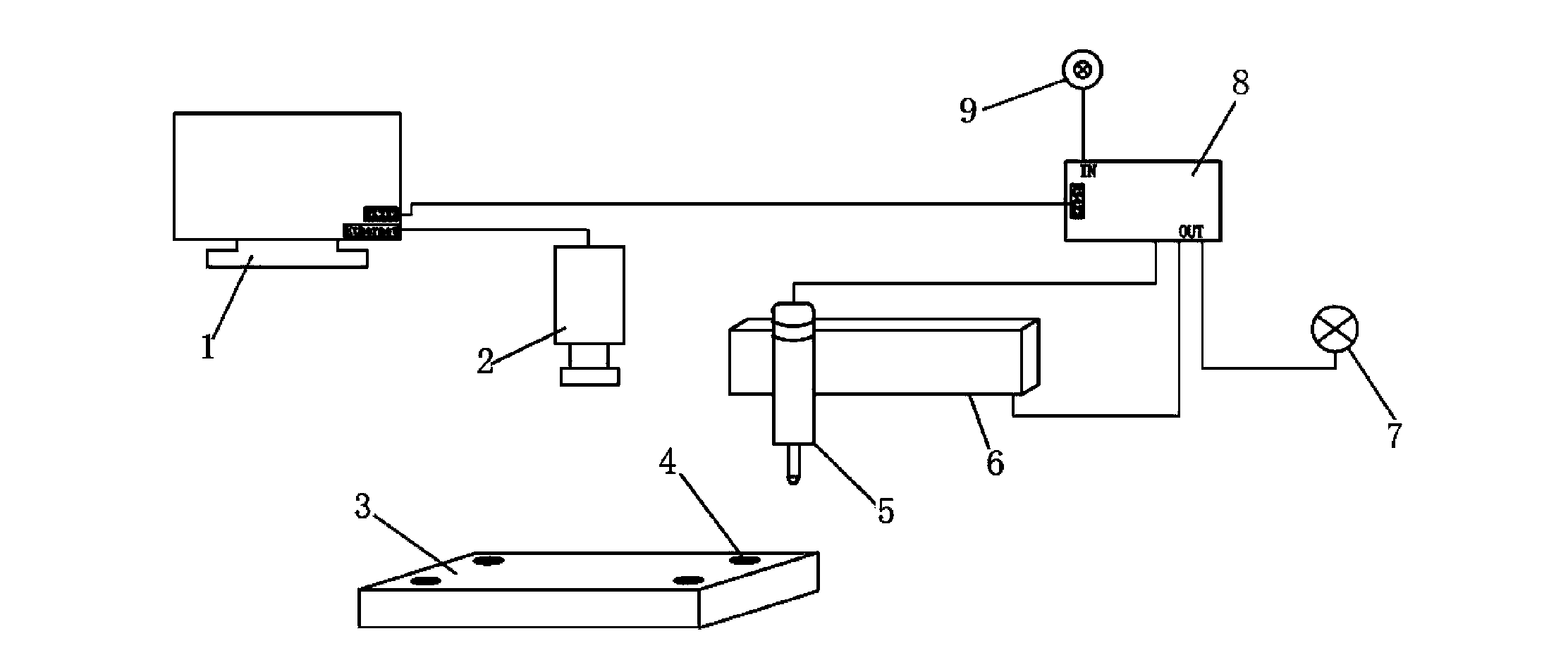
[0015] like figure 1 As shown, a computer vision-based automatic screw locking device of the present invention includes an industrial computer 1, an industrial camera 2, an electric screwdriver 5, a three-axis positioning device 6, a programmable controller 8 and an equipment rack (not shown in the figure ), wherein the three-axis positioning device 6 is arranged in the equipment rack, the electric screwdriver 5 is connected to the three-axis positioning device 6, the control end of the three-axis positioning device 6 and the electric screwdriver 5 The control terminals are respectively connected to the programmable controller 8, the programmable controller 8 is connected to the industrial computer 1 through the communication interface, and the industrial camera 2 is connected to the industrial computer 1.

[0016] Further, the industrial camera 2 is connected to the industrial computer 1 through an Ethernet network.

[0017] Further, a positioning jig (not shown in the figur...


PUM


Abstract

The invention relates to an automatic screw locking device based on the computer vision. The automatic screw locking device based on the computer vision comprises an industrial computer, an industrial camera, a power-driven screw driver, a three-axis positioning device, a programmable controller and a device rack. The three-axis positioning device is arranged in the device rack. The power-driven screw driver is connected in the three-axis positioning device. The control end of the three-axis positioning device and the control end of the power-driven screw driver are respectively connected with the programmable controller which is connected with the industrial computer through a communication interface. The industrial camera is connected with the industrial computer. According to the automatic screw locking device based on the computer vision, the machine vision is used for positioning a screw hole and affection by position deviation does not exist. The coordinates of the position of a screw hole will be calculated for one time when each product is machined so that positioning can be accurate. A control line is simple, clear and convenient to check if a fault exists. Real-time data including the coordinates of the position, position numbers, torque values and the like of screw assembly can be visually displaed. In addition, after locking is finished, whether all screws are well locked or not is detected online, maintenance is convenient and working efficiency is high.

Description

Technical field: [0001] The invention relates to the electrical field, in particular to a control device on an assembly production line, in particular to an automatic screw locking device based on computer vision. Background technique: [0002] In the product assembly line, there are often products that need to be assembled with a large number of screws. The efficiency of manual assembly is very low, and it is difficult to control the situation of missing screws. Therefore, automatic screw assembly technology is required in the prior art. In the prior art, the position data of each screw of the product is obtained in advance through manual teaching, and then the data is stored in the designated data register of the programmable controller, and the screw installation machine is driven by the corresponding trigger signal. The pre-set trajectory automatically locks the screw. Because this control method has high requirements on the manufacturing accuracy of the product and the ...

Claims


Application Information

Patent Timeline
IPC IPC(8): B23P19/06
CPCB23P19/06
Inventor 刘文平李启斌邵司亮孙少武郭翠俞文璟季照明阮连锋俞强
Owner YANFENG VISTEON AUTOMOTIVE ELECTRONICS
Why Eureka
Try Eureka