Controllable semi-automatic tool

A semi-automatic cutting tool technology, applied in the direction of manufacturing tools, wood processing equipment, multi-purpose machinery, etc., can solve the problem of low cutting efficiency, achieve the effect of improving cutting efficiency, saving complicated steps, and easy operation

Active Publication Date: 2014-03-26
惠州市翔凯精密制品有限公司
View PDF6 Cites 0 Cited by
  • Summary
  • Abstract
  • Description
  • Claims
  • Application Information

AI Technical Summary

Problems solved by technology

[0004] The invention solves the problem of low cutting efficiency by setting a controllable semi-automatic tool, and achieves the purpose of improving cutting efficiency

Method used


Image

  • Controllable semi-automatic tool

Examples


Embodiment 1

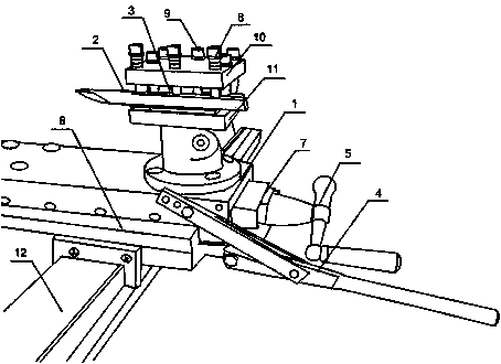
[0018] like figure 1 As shown, the present invention mainly includes a base 1, a blade 2, a cutter head 3, a slideway 6 and a hand pushing device, the hand pushing device is connected with the base 1 and the slideway 6 respectively, and the cutter head 3 is connected with the base 1, The base 1 is arranged on the slideway 6 , and the blade 2 is placed in the tool head 3 . The tool head 3 is placed on the base 1, the base 1 is set on the slideway 6, and the slideway 6 is placed on the clamping device or the guide rail 12 of the machine tool. Under the adjustment of the hand pushing device, the blade 2 is fixed in the tool head 3 and moves on the slideway 6 together with the base 1, so that the blade 2 is close to the wood for processing and polishing wood; in order to complete further processing, the hand pushing device is adjusted again , so that the cutter head 3 and the base 1 move on the clamping device or the guide rail 12 of the machine tool along with the slideway 6, so...

Embodiment 2

[0020] like figure 1 As shown, on the basis of Embodiment 1, the present embodiment includes a handle 5, a screw rod 7 and an automatic rod 4. The handle 5 is screwed to the slideway 6 through a bolt 7, and the automatic rod 4 is connected to the base 1 hinged connection. Rotate the handle 5, through the threaded cooperation between the screw rod 7 and the slideway 6, the base 1 moves along with the slideway 6 on the guide rail 12 of the machine tool or the clamping device; push the automatic rod 4 up and down to make the base 1 move on the slide Do linear motion on the road 6.

Embodiment 3

[0022] like figure 1 As shown, in this embodiment, on the basis of Embodiment 1, the cutter head 3 includes an upper baffle 10 and a lower baffle 11, the lower baffle 11 is provided with a connecting column 9, and the upper baffle 10 is fixed on the connecting column 9, Fastening bolts 8 are arranged between the two plates, and the blade 2 is placed between the upper baffle 10 and the lower baffle 11 . The upper baffle 10 and the lower baffle 11 are fixed by the connecting column 9 to form a space, adjust the position of the blade 2, and then fix the blade 2 on the tool head 3 by rotating the fastening bolt 8; the fastening can be adjusted according to different situations Bolts 8 are used to replace blades 2 of different types.


PUM


Abstract

The invention discloses a controllable semi-automatic tool which comprises a base, a blade, a tool head, a slide way and a hand-push device, wherein the hand-push device is connected with the base and the slide way respectively, the tool head is connected with the base, the base is arranged on the slide way, and the blade is arranged in the tool head. The tool head is arranged on the base, the base is arranged on the slide way, and the slide way is arranged on a clamping device or a guide rail of a machine tool. With the regulation of the hand-push device, the blade is fixed in the tool head and moves along with the base on the slide way, so that the blade is close to a timber to conveniently polish the timber; in order to complete the further processing, the hand-push device is secondarily regulated, so that the tool head and the base move on the clamping device or the guide rail of the machine tool along with the slide way to conveniently polish different parts of the timber. In the whole process, a round log is clamped to rotate, the tool moves at any time to cut in different modes, the complex procedures of fixing the tool and constantly moving the round log in the traditional processing craft are eliminated, and the working efficiency is improved.

Description

technical field [0001] The invention relates to the field of electromechanical control, in particular to a controllable semi-automatic tool. Background technique [0002] A cutting tool is a tool used for cutting in mechanical manufacturing, also known as a cutting tool. The tools used for cutting wood are called woodworking tools, and there is also a special type of tools used for geological exploration, well drilling, and mine drilling, called mining tools. Tools can be divided into five categories according to the surface of the workpiece: tools for processing various outer surfaces, including turning tools, planers, milling cutters, broaches and files for outer surfaces, etc.; hole processing tools, including drills, reamers, boring tools, etc. knives, reamers and inner surface broaches, etc.; thread processing tools, including taps, dies, automatic opening and closing thread cutting heads, thread turning tools and thread milling cutters, etc.; gear processing tools, in...

Claims


Application Information

Patent Timeline
Patent Type & Authority Applications(China)
IPC IPC(8): B27C9/00
Inventor 李胜峰
Owner 惠州市翔凯精密制品有限公司
Why Eureka
Try Eureka