Application method of cutting tool for reinforced concrete column forming steel die

A technology of concrete steel bars and cutting tools, which is applied in the direction of manufacturing tools, grinding workpiece supports, grinding/polishing equipment, etc., can solve the problems of low cutting efficiency, achieve the effect of improving cutting efficiency and easy operation

Inactive Publication Date: 2017-12-29
张贵友
View PDF0 Cites 0 Cited by
  • Summary
  • Abstract
  • Description
  • Claims
  • Application Information

AI Technical Summary

Problems solved by technology

[0003] The invention provides an application method of a cutting tool for a concrete reinforcement column forming steel mold to solve the problem of low cutting efficiency and achieve the purpose of improving cutting efficiency

Method used


Image

  • Application method of cutting tool for reinforced concrete column forming steel die

Examples


Embodiment 1

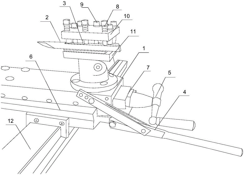
[0018] like figure 1 As shown, the present invention first places the steel on the clamping device on the tool, and the tool head is placed on the base, the base is arranged on the slideway, and the slideway is placed on the clamping device or the guide rail of the machine tool, and the tool head is placed on the base. Under the adjustment of the push device, the blade is fixed in the tool head and moves on the slide along with the base, so that the blade is close to the steel for processing and grinding steel, and the hand push device is adjusted again so that the tool head and the base move with the slide in the clamping device or It moves on the guide rail of the machine tool to facilitate the grinding of different parts of the steel; it includes the base 1, the blade 2, the tool head 3, the slideway 6 and the hand pushing device. The hand pushing device is connected to the base 1 and the slideway 6 respectively. The cutter head 3 is connected to the base 1 , the base 1 is ...

Embodiment 2

[0020] like figure 1 As shown, on the basis of Embodiment 1, the present embodiment includes a handle 5, a screw rod 7 and an automatic rod 4. The handle 5 is screwed to the slideway 6 through a bolt 7, and the automatic rod 4 is connected to the base 1 hinged connection. Rotate the handle 5, through the threaded cooperation between the screw rod 7 and the slideway 6, the base 1 moves along with the slideway 6 on the guide rail 12 of the machine tool or the clamping device; push the automatic rod 4 up and down to make the base 1 move on the slide Do linear motion on the road 6.

Embodiment 3

[0022] like figure 1 As shown, in this embodiment, on the basis of Embodiment 1, the cutter head 3 includes an upper baffle 10 and a lower baffle 11, the lower baffle 11 is provided with a connecting column 9, and the upper baffle 10 is fixed on the connecting column 9, Fastening bolts 8 are arranged between the two plates, and the blade 2 is placed between the upper baffle 10 and the lower baffle 11 . The upper baffle 10 and the lower baffle 11 are fixed by the connecting column 9 to form a space, adjust the position of the blade 2, and then fix the blade 2 on the tool head 3 by rotating the fastening bolt 8; the fastening can be adjusted according to different situations Bolts 8 are used to replace blades 2 of different types.


PUM


Abstract

The invention discloses an application method of a cutting tool for a steel mold for forming a concrete reinforcement column. Firstly, the steel is placed on the clamping device on the tool, and the tool head is placed on the base. The base is set on the slideway, and the slideway is placed on the On the clamping device or the guide rail of the machine tool, under the adjustment of the hand-push device, the blade is fixed in the tool head and moves on the slide along with the base, so that the blade is close to the steel for processing and grinding steel, and the hand-push device is adjusted again to make the tool The head and base move on the clamping device or the guide rail of the machine tool along with the slideway, so as to facilitate the grinding of different parts of the steel.

Description

technical field [0001] The invention relates to the field of electromechanical control, in particular to an application method of a cutting tool for a concrete reinforcement column forming steel mold. Background technique [0002] Tools can be divided into five categories according to the surface of the workpiece: tools for processing various outer surfaces, including turning tools, planers, milling cutters, broaches and files for outer surfaces, etc.; hole processing tools, including drills, reamers, boring tools, etc. knives, reamers and inner surface broaches, etc.; thread processing tools, including taps, dies, automatic opening and closing thread cutting heads, thread turning tools and thread milling cutters, etc.; gear processing tools, including hobs, gear shaping knives, gear shaving Knives, bevel gears and broaches, etc.; parting tools, including insert circular saw blades, band saws, bow saws, parting turning tools and saw blade milling cutters, etc. When cutting ...

Claims


Application Information

Patent Timeline
Patent Type & Authority Applications(China)
IPC IPC(8): B24B19/20B24B41/06
CPCB24B19/20B24B41/068
Inventor 张贵友
Owner 张贵友
Why Eureka
Try Eureka