Supercharge Your Innovation With Domain-Expert AI Agents!

Method for cooling a mould by circulating a heat-transfer fluid in contact with the external face thereof

一种传热流体、外表面的技术,应用在家里用具、其他家里用具、家用元件等方向,能够解决复杂、传热流体回路的模具昂贵实现等问题

Inactive Publication Date: 2014-03-26
SIDEL PARTICIPATIONS SAS
View PDF5 Cites 7 Cited by
  • Summary
  • Abstract
  • Description
  • Claims
  • Application Information

AI Technical Summary

Problems solved by technology

[0012] Manufacturing molds with dedicated heat transfer fluid circuits for cooling is extremely expensive and complex to implement due to thermal resistance within the thickness of the mold

Method used


Image

  • Method for cooling a mould by circulating a heat-transfer fluid in contact with the external face thereof
  • Method for cooling a mould by circulating a heat-transfer fluid in contact with the external face thereof
  • Method for cooling a mould by circulating a heat-transfer fluid in contact with the external face thereof

Examples


Embodiment Construction

[0033] In the remainder of the specification, elements having the same structure or similar functions will be denoted by the same reference numerals.

[0034] In the remainder of the specification, the following directions will be used without limitation:

[0035] - longitudinal, indicated by arrow "L" and oriented from rear to front;

[0036] - vertically, indicated by an arrow "V" and oriented upwards from the bottom;

[0037] - Transverse, indicated by arrow "T" and oriented from left to right.

[0038] Additionally, the terms "axial" and "radial" will be used with reference to the axis "A".

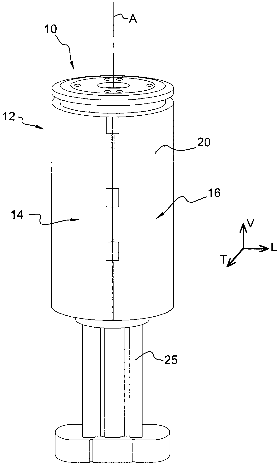
[0039] figure 1 A device 10 for producing containers by blow molding or by stretch blow molding is shown. The device 10 comprises a mold 12 formed by joining two substantially symmetrical mold halves 14, 16 made of metallic material, for example steel or an aluminum alloy.

[0040] The mold 12 thus assembled has the overall shape of a hollow cylinder rotating about a vertical mai...


PUM


Abstract

Method and apparatus for cooling a heated mould (12, 14, 16) of a device (10) for blow-moulding thermoplastic containers, the device including: a mould (12, 14, 16) having an internal face which delimits a moulding cavity (18) and which includes an external face (20, 28) which surrounds the moulding cavity (18); heating elements for heating the mould to a determined temperature and which are deactivated when the cooling method is implemented; characterized in that the mould (12, 14, 16) is cooled by circulating heat-transfer fluid directly in contact with the external face (20, 28) thereof.

Description

technical field [0001] The invention relates to a method for cooling a heated mold of a device for blow molding thermoplastic containers. [0002] More specifically, the present invention relates to a method for cooling a heated mold of an apparatus for blow molding thermoplastic containers, said apparatus comprising: [0003] - a mold having an inner surface defining a molding cavity and comprising an outer surface surrounding the molding cavity; [0004] - Heating means for heating the mold to a defined temperature and deactivated when the cooling method is carried out. Background technique [0005] In a known manner, molding devices of this type can be used to produce containers, such as bottles, from thermoplastic preforms. The preforms are preheated to the glass transition temperature in order to render them sufficiently plastic. The thus heated preform is inserted into the molding cavity, and the blow molding nozzle injects pressurized blow molding fluid (usually ai...

Claims


Application Information

Patent Timeline
Patent Type & Authority Applications(China)
IPC IPC(8): B29C49/48B29C49/64
CPCB29C49/4823B29C2049/4858B29C49/48B29C2049/4864B29C49/28B29L2031/7158B29C2049/4825
Inventor A·勒佩舒尔L·富埃
Owner SIDEL PARTICIPATIONS SAS
Features
  • R&D
  • Intellectual Property
  • Life Sciences
  • Materials
  • Tech Scout
  • Unparalleled Data Quality
  • Higher Quality Content
  • 60% Fewer Hallucinations
Learn More