Managed pressure cementing

a pressure cementing and pressure technology, applied in the direction of survey, sealing/packing, borehole/well accessories, etc., can solve the problems of insufficient data to effectively measure the success or failure of a primary cement job, the inefficiency of primary cementing of problematic wells, and the inability to cement problematic wells

Active Publication Date: 2013-05-16
WEATHERFORD TECH HLDG LLC
View PDF25 Cites 166 Cited by
  • Summary
  • Abstract
  • Description
  • Claims
  • Application Information

AI Technical Summary

Benefits of technology

[0007]Embodiments of the present invention generally relate to managed pressure cementing. In one embodiment, a method of cementing a tubular string in a wellbore includes: deploying the tubular string into the wellbore; pumping cement slurry into the tubular string; launching a cementing plug after pumping the cement slurry; propelling the cementing plug through the tubular string, thereby pumping the cement slurry through the tubular string and into an annulus formed between the tubular string and the wellbore; and controlling flow of fluid displaced from the wellbore by the cement slurry to control pressure of the annulus.

Problems solved by technology

Not all wells that are drilled and casing strings cemented in place during the well operation are problematic.
Conversely, primary cementing of problematic wells has historically been inefficient to unobtainable by manipulation of the traditional variables.
What can be recorded today to effectively measure the success or failure of a primary cement job is not adequate for cementing problematic wells.
Whether success is a leak-off test, open-hole kick-off plug, isolation of a hydrocarbon bearing zone of interest, or a fresh water zone that must be hydraulically or mechanically isolated and protected, the tools and methods that operators and service companies employ today that can be controlled and monitored are not always enough to provide the expected nor the desired results.

Method used


Image

  • Managed pressure cementing
  • Managed pressure cementing
  • Managed pressure cementing

Examples


Embodiment Construction

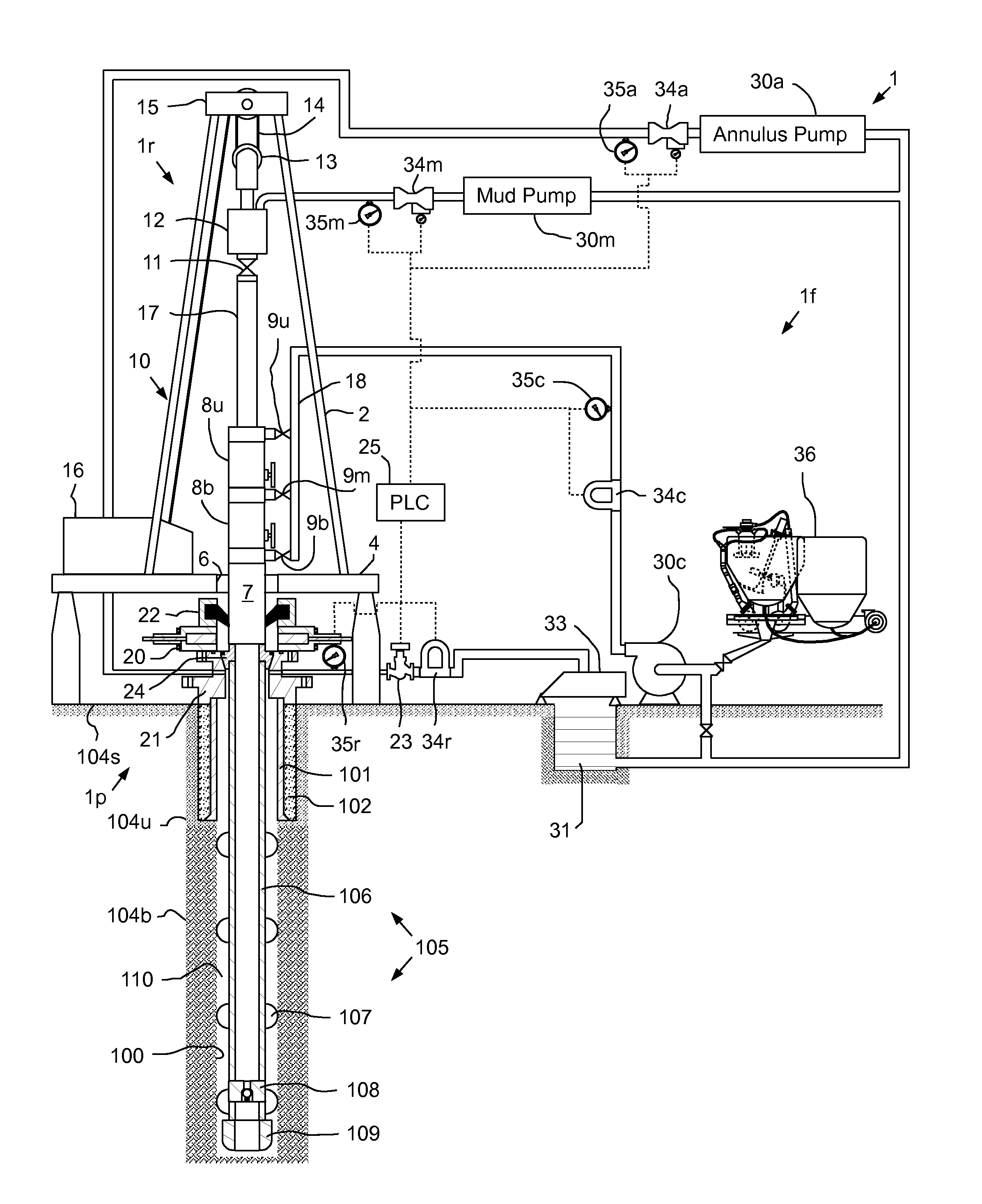
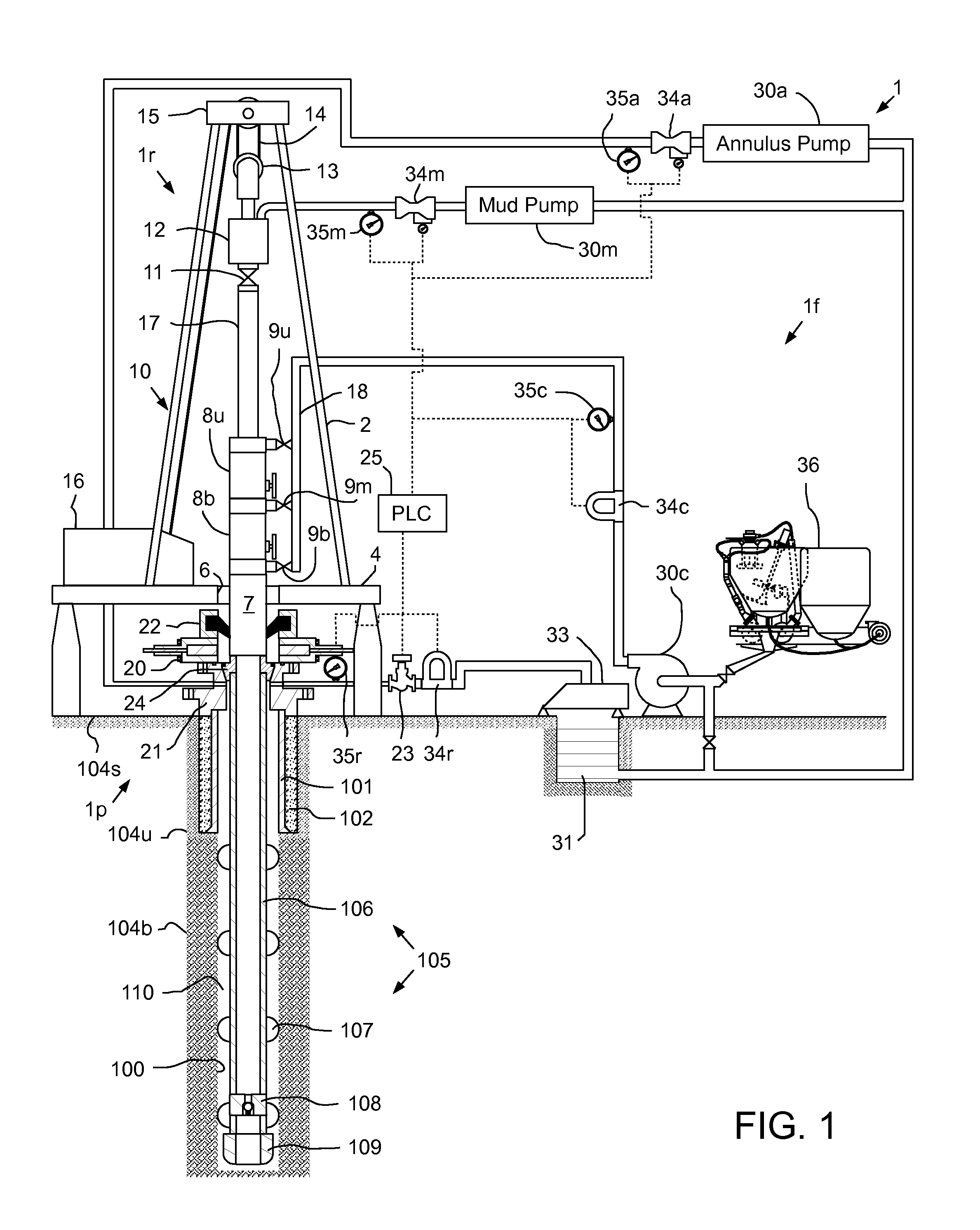
[0023]FIG. 1 illustrates a terrestrial drilling system 1 in a casing cementing mode, according to one embodiment of the present invention. The drilling system 1 may include a drilling rig 1r, a fluid handling system 1f, and a pressure control assembly (PCA) 1p. The drilling rig 1r may include a derrick 2 having a rig floor 4 at its lower end having an opening 6 through which a casing adapter 7 extends downwardly into the PCA 1p. The PCA 1p may be connected to a wellhead 21. The wellhead 21 may be mounted on an outer casing string 101 which has been deployed into a wellbore 100 drilled from a surface 104s of the earth and cemented 102 into the wellbore. The casing adapter 7 may include a seal head (not shown) for engaging an inner casing string 105 which has been deployed into the wellbore 100 and is ready to be cemented into place. The casing adapter 7 may also be connected to a cementing head 10. The cementing head 10 may also be connected to a Kelly valve 11 via spool 17. The Kell...


PUM

PropertyMeasurementUnit
depthaaaaaaaaaa
pressureaaaaaaaaaa
flow rateaaaaaaaaaa

Abstract

A method of cementing a tubular string in a wellbore includes: deploying the tubular string into the wellbore; pumping cement slurry into the tubular string; launching a cementing plug after pumping the cement slurry; propelling the cementing plug through the tubular string, thereby pumping the cement slurry through the tubular string and into an annulus formed between the tubular string and the wellbore; and controlling flow of fluid displaced from the wellbore by the cement slurry to control pressure of the annulus.

Description

BACKGROUND OF THE INVENTION[0001]1. Field of the Invention[0002]Embodiments of the present invention generally relate to managed pressure cementing.[0003]2. Description of the Related Art[0004]In wellbore construction and completion operations, a wellbore is formed to access hydrocarbon-bearing formations (e.g., crude oil and / or natural gas) by the use of drilling. Drilling is accomplished by utilizing a drill bit that is mounted on the end of a drill string. To drill within the wellbore to a predetermined depth, the drill string is often rotated by a top drive or rotary table on a surface platform or rig, and / or by a downhole motor mounted towards the lower end of the drill string. After drilling to a predetermined depth, the drill string and drill bit are removed and a section of casing is lowered into the wellbore. An annulus is thus formed between the string of casing and the formation. The casing string is hung from the wellhead. A cementing operation is then conducted in order...

Claims


Application Information

Patent Timeline
Patent Type & Authority Applications(United States)
IPC IPC(8): E21B33/16E21B33/14E21B47/00
CPCE21B33/16E21B47/0005E21B33/13E21B47/0001E21B33/143E21B33/165E21B47/005E21B47/001E21B33/14
Inventor HANNEGAN, DON M.PENA, CESARPAVEL, DAVIDGRAYSON, MICHAEL BRIANBOUTALBI, SAIDCOOPER, TODD DOUGLASDUNN, TIMOTHY P.ZAMORA, JR., FRANK
Owner WEATHERFORD TECH HLDG LLC
Why Eureka
Try Eureka