
Rotary electroplating machine and automatic discharger thereof

A technology of automatic unloading device and electroplating machine, which is applied in the direction of electrolysis process, electrolysis components, cells, etc., can solve the problems of time-consuming and laborious, material leakage, material jamming, etc.

Active Publication Date: 2014-03-26
SHENZHEN SUNLORD ELECTRONICS
View PDF6 Cites 2 Cited by
  • Summary
  • Abstract
  • Description
  • Claims
  • Application Information

AI Technical Summary

Problems solved by technology

Since the automatic unloading function of rotary electroplating machines in the industry usually has problems such as dirty automatic unloading, material jamming, and material leakage, most rotary electroplating machines simply do not have automatic unloading functions, and the lower end of the cathode ring is directly covered with plastic. The back cover of the material, after electroplating, requires manual operation to remove the cathode ring from the equipment, and pour out the material sheet separately. When electroplating again, the cathode ring needs to be installed on the equipment, which is time-consuming and laborious

Method used


Image

  • Rotary electroplating machine and automatic discharger thereof
  • Rotary electroplating machine and automatic discharger thereof
  • Rotary electroplating machine and automatic discharger thereof

Examples


Embodiment Construction

[0037] The present invention will be further described below with reference to the accompanying drawings and in combination with preferred embodiments.

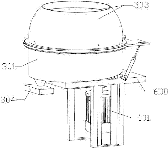
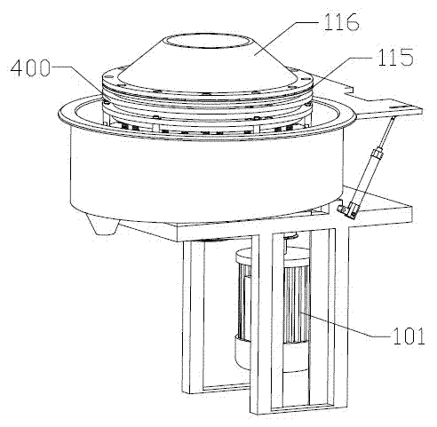
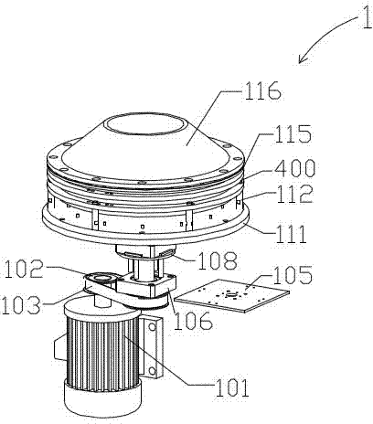
[0038] like figure 1 and figure 2 As shown, the invention discloses a rotary electroplating machine, which is used for electroplating and unloading of chip components. like figure 1 , image 3 , Figure 8 and Figure 11 As shown, the rotary electroplating machine of the preferred embodiment of the present invention includes a cathode ring rotation mechanism 1, an automatic separation mechanism 2, a discharge mechanism 3, a cathode ring 400, a rubber disc 500, a frame 600, and an anode titanium cylinder (not shown in the figure) ) and a rectifier (not shown). During the electroplating production of the rotary electroplating machine, the anode titanium cylinder (not shown in the figure) is lowered into the cathode ring 400, and the plating solution is continuously replenished in the cathode ring 400, and the cathode ring...


PUM


Abstract

The invention discloses a rotary electroplating machine and an automatic discharger thereof. The rotary electroplating machine, which is used for electroplating and discharging chip elements, comprises a cathodal ring, a cathodal ring-rotating mechanism and the automatic discharger, the cathodal ring is controlled by the cathodal ring-rotating mechanism to rotate, the automatic discharger comprises a base plate and an automatic separating mechanism, and the base plate and the cathodal ring are controlled by the automatic separating mechanism to be closed and be separated from each other. Because the rotary electroplating machine utilizes the automatic separating mechanism to control the closing and separation between the base plate and the cathodal ring, the rotary electroplating machine can electroplate and discharge chip elements; during electroplating, the cathodal ring and the base plate are closed; when materials need to be discharged, the cathodal ring and the base plate are separated from each other, so that a gap is formed, as a result, the chip elements can be thrown out from the gap along with water flow during rotation, consequently, the step of automatic discharge is complete, and the materials can be discharged thoroughly.

Description

technical field [0001] The invention relates to a rotary electroplating machine, in particular to a rotary electroplating machine for chip components and an automatic unloading device thereof. Background technique [0002] The electroplating method of the existing chip components generally adopts the electroplating method of the rotary electroplating machine, and the common electroplating methods such as rack plating and barrel plating. The quality effect of the electroplating chip components of the rotary electroplating machine is better. Since the automatic unloading function of rotary electroplating machines in the industry usually has problems such as dirty automatic unloading, material jamming, and material leakage, most rotary electroplating machines simply do not have automatic unloading functions, and the lower end of the cathode ring is directly covered with plastic. The back cover of the material, after electroplating, requires manual operation to remove the cathod...

Claims


Application Information

Patent Timeline
Patent Type & Authority Applications(China)
IPC IPC(8): C25D7/00C25D21/00
Inventor 曾艳军蒋家军
Owner SHENZHEN SUNLORD ELECTRONICS
Learn More