Supercharge Your Innovation With Domain-Expert AI Agents!

Spray-suction electroplating tank

An electroplating tank and spray-suction technology, applied in the plating tank and other directions, can solve the problems of uneven thickness, drawing time, and increased product defect rate, and achieve the effect of uniform thickness and increased yield.

Active Publication Date: 2016-05-11
郑振华
View PDF6 Cites 0 Cited by
  • Summary
  • Abstract
  • Description
  • Claims
  • Application Information

AI Technical Summary

Problems solved by technology

According to the requirements, there are holes on the circuit board, and the electroplating solution must penetrate into the holes to plate the product in the holes; however, due to the increasingly finer products today, the smaller the holes, the larger the depth ratio. The immersion plating method is used to operate the electroplating, and the electroplating solution is difficult to enter the small holes of the circuit board, resulting in such as Figure 5 As shown, the thickness of the plating in the hole 7 is insufficient or the defective rate of the product is increased due to the uneven thickness of the plating product 71 inside and outside the hole
[0003] In order to solve the above problems, the method adopted by the known technology is to use a very low current and prolong the time for electroplating. This method not only prolongs the time required for the process, but also the plated product has rough crystals and poor ductility. Some other disadvantages; in addition, the cost of equipment required for electroplating at low currents is also greatly increased, so it is urgent to improve the known electroplating technology

Method used


Image

  • Spray-suction electroplating tank
  • Spray-suction electroplating tank
  • Spray-suction electroplating tank

Examples


Embodiment Construction

[0020] The following examples illustrate possible implementations of the present invention, but they are not intended to limit the protection scope of the present invention and are described in advance.

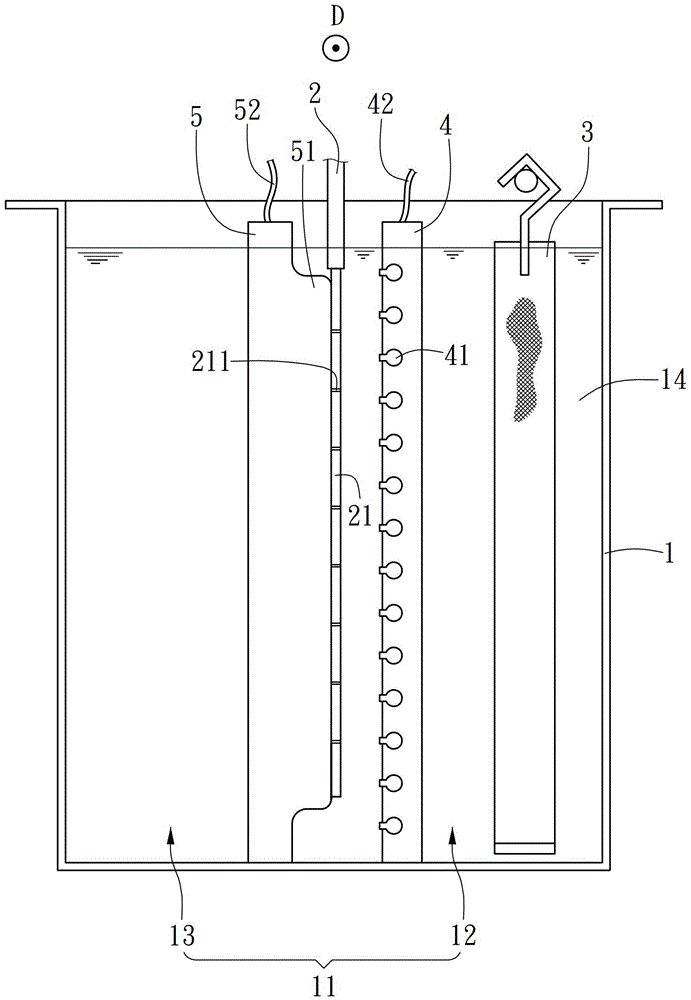
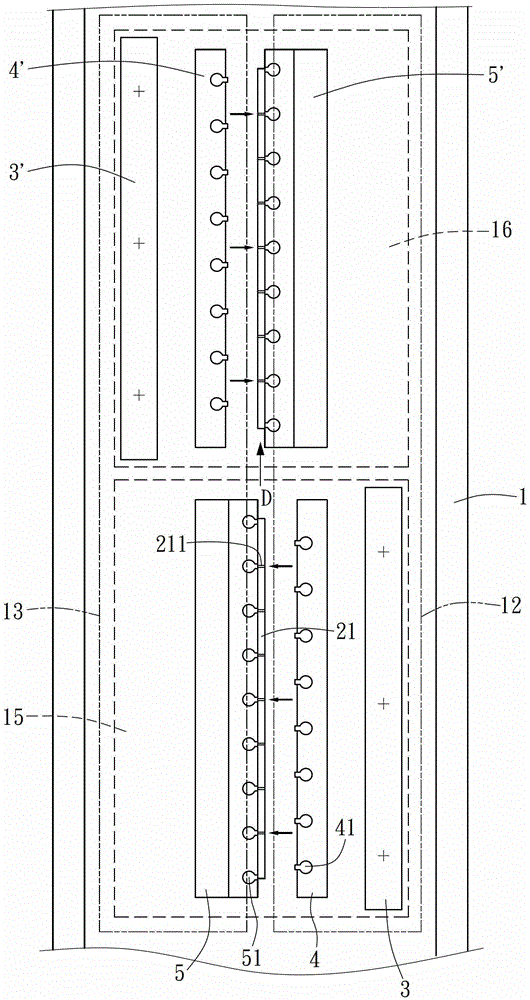
[0021] see figure 1 , which is a schematic plan view of the spray-suction electroplating tank provided by the present invention, which includes a tank body 1, which has an accommodating space 11 for containing the electroplating solution 14 in the tank body 1, and in the accommodating space 11 A cathode electrode 2 is provided in the center, and the cathode electrode 2 can be connected to a through hole 211 and defined to extend along a longitudinal direction D (in figure 1 The object to be plated 21 in the vertical direction of the drawing), wherein the object to be plated 21 divides the accommodating space 11 into two half-side spaces 12, 13, and an anode electrode is arranged in the space 12 on one side 3. The electroplating product can be plated on the object to be pla...


PUM


Abstract

The invention discloses an ejection-suction electroplating bath. The ejection-suction electroplating bath is provided with a bath body in which a cathode electrode is arranged, the cathode electrode can be connected with an electroplated object with a through hole, an anode electrode and an ejection device are arranged on one side of the electroplated object in the bath, the ejection device is provided with a nozzle which faces the electroplated object and is used for ejecting electroplate liquid to the electroplated object, a suction device is arranged on the other side of the electroplated object in the bath, the suction device is provided with a suction inlet, and used for sucking the electroplate liquid in the bath, and enabling the electroplate liquid in the bath to flow from the ejection deice to the suction device in cooperation with the ejection device, so that the electroplate liquid is helped to enter the hole of the electroplated object, and an electroplating product can be electroplated in the hole. The ejection-suction electroplating bath disclosed by the invention has a beneficial effect that the thickness of the electroplating product in the hole can be uniform, thereby increasing the yield of the product.

Description

technical field [0001] The invention relates to the design of an electroplating tank, in particular to an electroplating tank in which an electroplating solution flows through a hole through a spraying and suction device. Background technique [0002] The known electroplating technology refers to immersing the cathode electrode in the electroplating solution containing cations, and the cations in the electroplating solution are combined with the anions of the cathode electrode through the flow of electrons, and a layer of product is attached on the cathode electrode. This is the case with circuit printing technology. According to the requirements, there are holes on the circuit board, and the electroplating solution must penetrate into the holes to plate the product in the holes; however, due to the increasingly finer products today, the smaller the holes, the larger the depth ratio. The immersion electroplating method is used to operate the electroplating, and the electrop...

Claims


Application Information

Patent Timeline
Patent Type & Authority Patents(China)
IPC IPC(8): C25D17/02C25D5/08
Inventor 郑振华
Owner 郑振华
Features
  • R&D
  • Intellectual Property
  • Life Sciences
  • Materials
  • Tech Scout
  • Unparalleled Data Quality
  • Higher Quality Content
  • 60% Fewer Hallucinations
Learn More